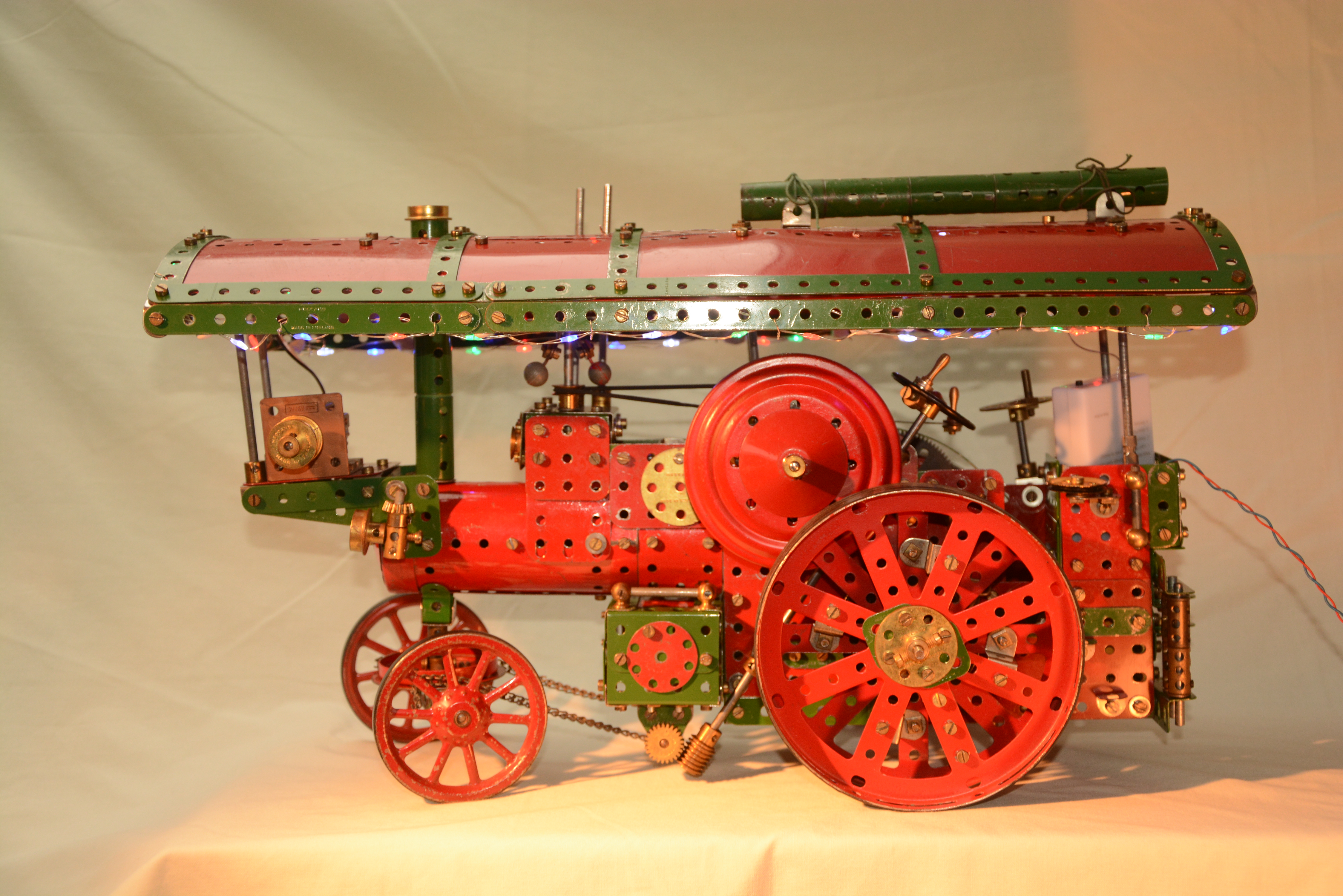
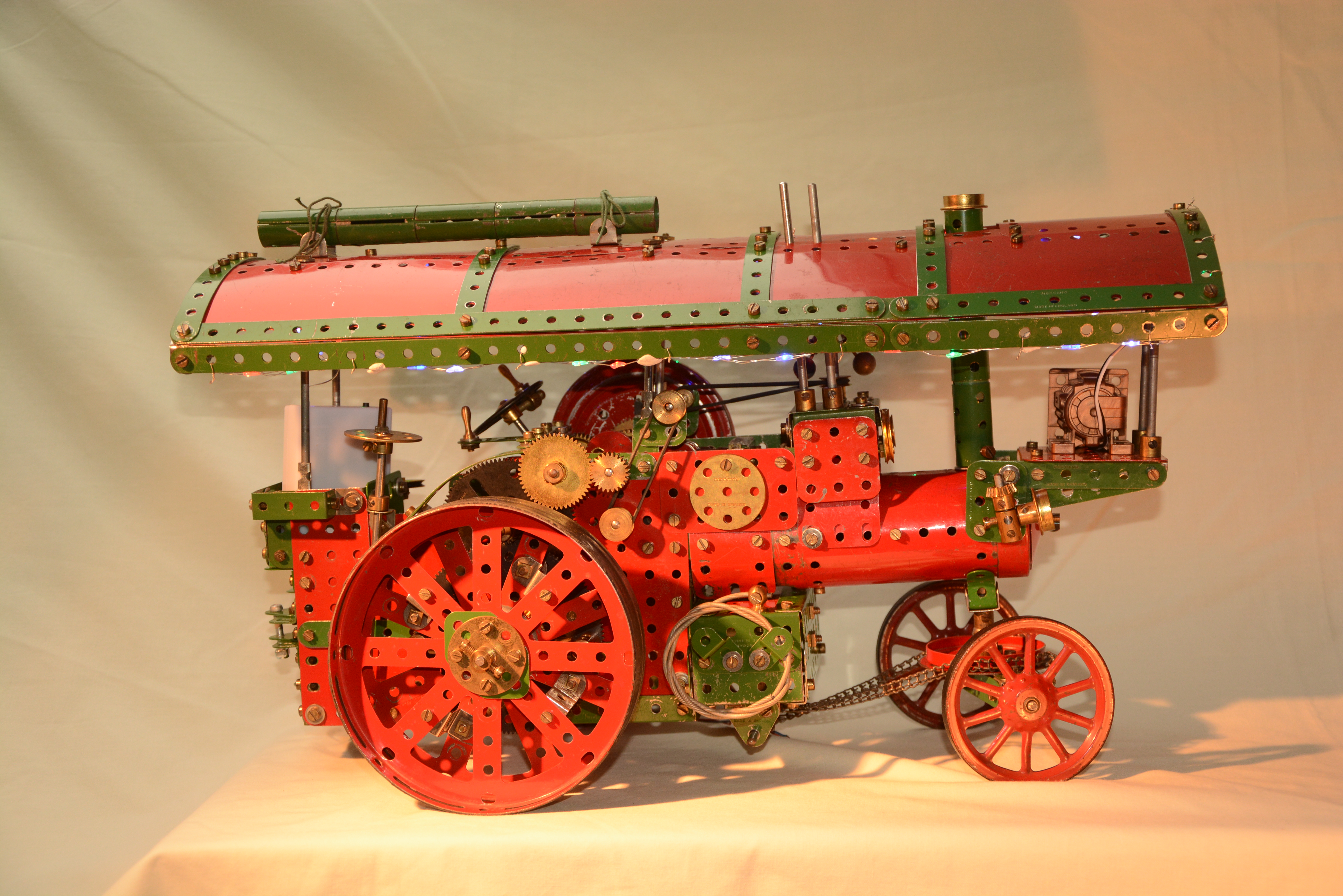
Meccano Model of Foster's (Lincoln) LR class Showman’s Road Locomotive
Prototype
These 7-8nhp (Nominal Horse Power) engines were the juggernauts of their day, pulling loads of up to 50 tons on a train of as many as 5 wagons which might include the living van for the family. As well as towing the fairground rides from one site to the next, the bright colours, polished metal and lights acted as a travelling advertisement, and on arrival at the field the engine would employ its winch to help erect the structures for the attractions. When the fair opened, the flywheel would be connected to a powerful dynamo which could generate up to 300 amps at 110 volts to power the lights and electrically driven rides such as dodgems. The overall roof protected not only the driver, but also the dynamo from the elements. When the Fair closed late at night, the rides would all be dismantled and packed up to be towed away in the early hours to the next site – a hard working life! Water and coal were picked up where possible along the way, the former from any convenient pond or stream every 10 miles or so. A hose is modelled on the R side water tank.
Fosters produced around 68 of these larger Road locomotives between 1885 and 1934, and their Princess Marina was the last such engine ever produced. After the war there were many Army Surplus diesel tank transporter tractors such as Scammels which tended to take over, but steam was still used to tow fairs into the 1950s. Fosters were involved in the design and production of tanks in WW1 so their logo from then on incorporated an image of the tank. Distinctive features of their engines include the brackets for the dynamo, and simpler supports for the roof.
The Model
Typically these vehicles had 2 cylinders run as a compound engine (the lower pressure cylinder using exhaust steam from the high pressure side) connected to a double crankshaft – modelled by single eccentrics due to lack of space. They had 3 gears (2 on the model) - gear changing could only take place when the vehicle was stationary as there was no clutch! The screw brake operating on the inside of the rear wheel (dummy on the model) was really only for parking – braking during travel was done through the engine (shutting off steam and moving the reversing mechanism to mid-position), which put a strain on linkages and gears.
Steering is done by the steersman sitting on the seat on the near (L) side so that the kerb can be followed – oncoming vehicles are likely to leave a wide berth when facing an engine weighing 10-20 tons! The stoker/driver would also look out on the R side. This model demonstrates a differential built into the R hand wheel, as tight turns were needed getting into fields. The flywheel is solid, not spoked, as on most steam engines designed to run on roads – supposedly less likely to frighten horses!
The winch is shown fixed to the back axle; to operate it, the wheels were chocked and the left wheel uncoupled from the axle (a long screw on the model), allowing the differential to drive the winch at double speed. Simple cranes could be constructed from spars and pulleys on the rear drawbar hitching point for wagons, and the rope run to them between rollers.
At the fairground, the chimney extension would be erected to take sparks and smoke away from the tents and rides, and the belt drive connected from the rim of the flywheel to the dynamo (here modelled by a motor, which when back-driven can generate around 1 v. AC). A non-Meccano string of LEDs adds colour and character to the final appearance.


