Controlling the first functions....
With a few of the systems in place, a control box was needed for demonstration at meetings. None of the systems need any electronics or computer control, as the intention was to keep it simple, and helped meet my requirement of reliability.
Mechanisms and basic electrics are easy to troubleshoot, and are less prone to throwing a wobbly than more complex arrangements. The control box is a plywood construction with a brushed aluminium faceplate. Inside are rows of connector blocks farming out the input power to the switches, and collecting the earth return.
The power supply is from a 7.5v DC transformer salvaged from an old video camera battery charger, or a 6v lamp battery when mains aren’t available. A variety of toggle switches – some centrally sprung – plus momentary push buttons for turret 'firing’ send power to the ship.
Initially the wires were just bundled, but were later replaced by a Scart cable and a Cat V cable.
These cables were chosen for their multiple cores and conveniently compact connectors. Note the big red pushbutton. This fires a ‘broadside’ with a single touch instead of pushing the three individual buttons down simultaneously.
This did necessitate having diodes between it and the 3 fire buttons, else pressing any of the three would have set all 3 off. The switches are all arranged in the same layout as positioned on the model (when the bow is to the right), and the toggle switches move in the direction of the function.
The turrets …..
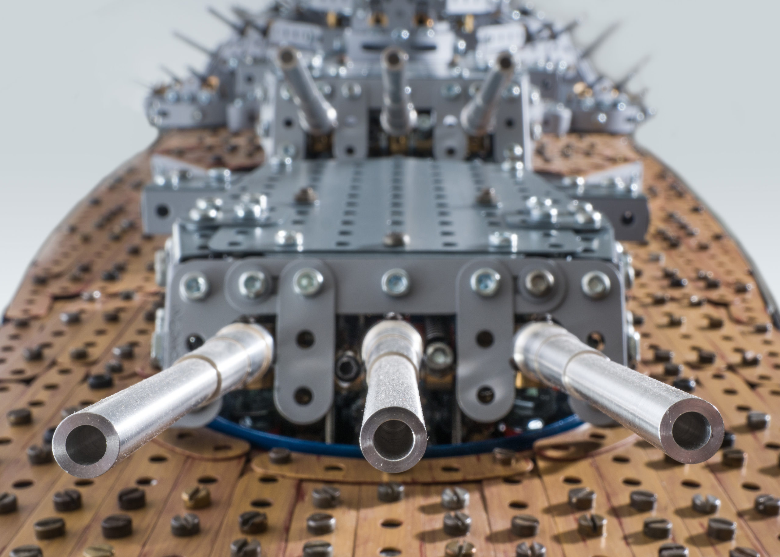
A battleship is all about the big guns, and this model is no different. The turrets are multi-functional with rotation, gun elevation, and barrel recoil. The real turrets were "three gun turrets" because each barrel could be individually elevated. The model has "triple gun turrets" because the barrels move in unison.
It was always the intention not to have any electrical connections across the section joins. This was to ease assembly, as otherwise there would be trailing leads to plug together and tuck away whilst trying to offer the sections together. I wouldn’t have enough hands! It also meant that the weight and volume of the motors and gearboxes would be in the centre section rather than inside the bow and stern sections. The upshot is that a turret mechanism only had to provide the motions and not the motive power, so less to fit into the space.
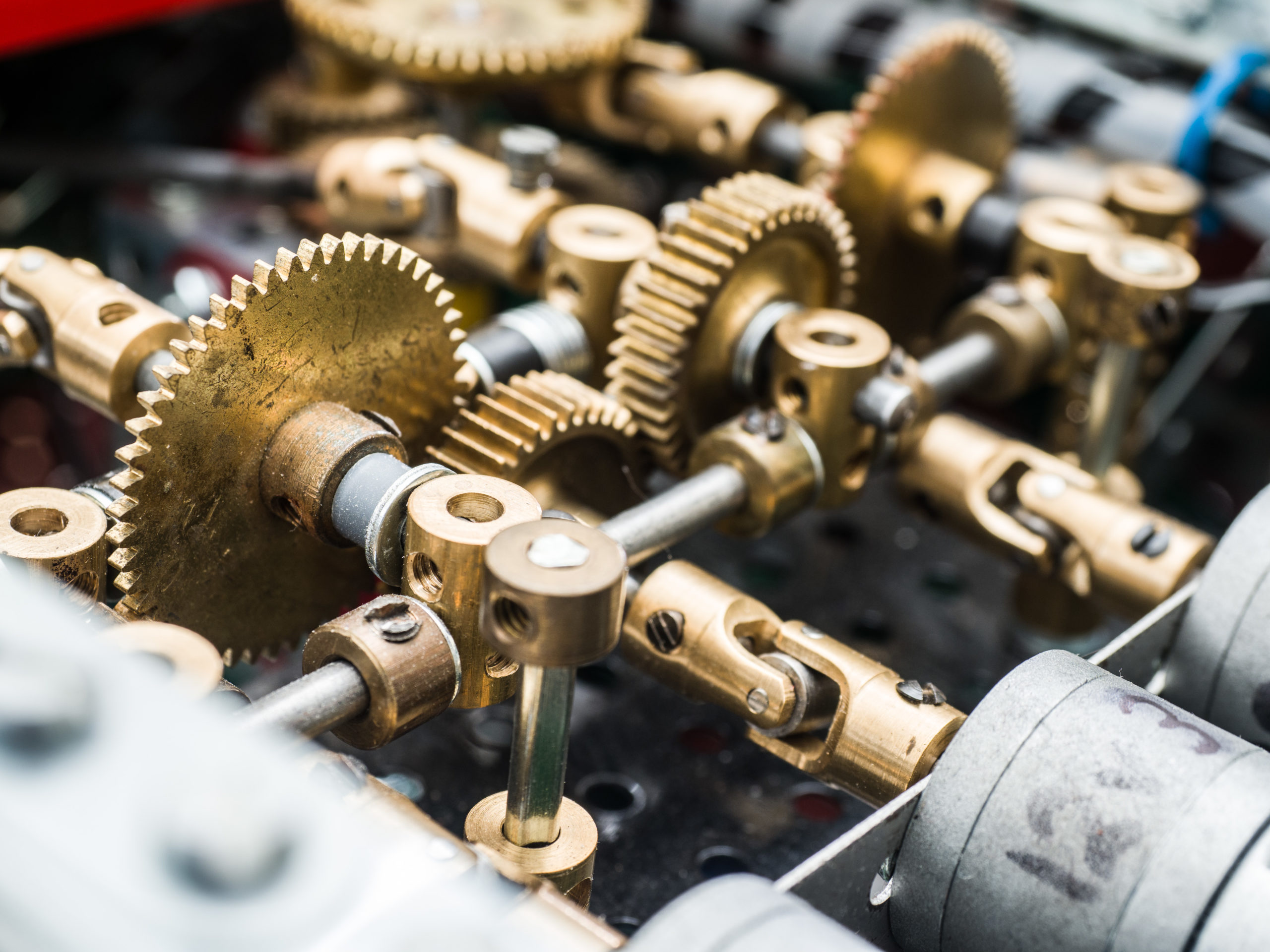
All the motors in the model are 4mm ‘D’ shaft gearhead motors with a variety of gearhead ratios. Each turret requires four motors; rotation, elevation, fire and recoil reset. The other functions of rudders, propellers and anchors each need one. There are three near identical motor/gearbox modules mounted in the centre section. Each module serves a turret rotation and gun elevation, and two of the modules include a motor for rudders and anchors.
As access is tight, the two lower modules are secured in place simply by two ‘thumb screws’ seen in the photos as collars on tri-axles, at each side of the module. The rods have short threaded couplings at their ends which tighten down onto fixed locating bolts.
The gears in the modules are on layshafts supported at each end, all supported by brass bearings. The output from the motors each connect to a ‘Stuart Borrill’ U/J onto a layshaft. In this way, each motor only supplies torque without seeing side load. The rear end of each motor is supported by a plastic strip to relieve the bending on the front attachment.
The drives from the motors utilise many U/J’s for feeding the shafts through the length of the model.
Each turret mechanism is housed in a turret chassis. The drive for the barrel elevation is on the same axis as the turret rotation, so the turret can rotate without affecting the elevation. The drive input for rotation is the large bevel gear, which has the chassis mounted from it. Thus driving the gear around rotates the turret.
Elevation is achieved using a central screwed rod. Using a short threaded coupling it extends up from the rod above the bevel gear. When driven via the small contrate it drives a threaded boss up or down it.
This motion is translated via a linkage to change the angle of a barrel ‘carriage’ (made using rods, short couplings and handrail couplings) which is pivoted to the front of the chassis.
The tension spring just visible is to bias the carriage over in one direction to remove elevation backlash.
To achieve recoil, the barrel carriage has a secondary carriage pivoted low to the first (see white line axis), to which the ends of the barrel rods are attached. This secondary carriage pivots forward against a Meccano compression spring (red arrow, but hidden from view) by a Meccano Bowden cable pulling between two points (see yellow arrow).
When released, the barrel rods snap back, sliding through the holes of short couplings. It was key to get everything exactly lined up and with dead straight rods.
This video shows the turret mechanisms and the recoil action.
The reaction point for the remote end of the cable sleeve is in a threaded coupling, which also holds a vertical rod. This rod inserts into a hole when lowering the turret into position to ‘earth’ the reaction. A little after this locates, the holes in each end of a 5 hole strip (doubled up to resist bending) locate over rods, and rests on collars. This allows the whole turret to be supported whilst remaining clear of the driving gears. Once lowered into position, both driving gears are meshed ready for action.
When the turret is in position, the remote end of the Bowden Cable is looped over a bolt protruding from the side of a 133 tooth gear close to the gear’s centre.
A worm driven by the recoil reset motor drives the gear around thus pulling the cable, until a microswitch is tripped to stop the motor. The presence of the worm locks the gear from moving until next time. The recoil reset is an autonomous action, requiring no input from the operator. This is the purpose of the local 6v battery packs close to each turret, as they supply power via the microswitches to the reset motors.
The Meccano battery packs each have an on-off lever which must be set to ‘on’ before the ship’s sections are assembled, as access afterwards is not possible. Each lever is connected to a rod which protrudes out the end of the bow section and stern section. Pushing this rod turns on the battery pack.
To mitigate the times when I forget to turn them on in this manner, there is now an opposing ‘anvil’ (large washer) on the centre section such that the action of joining the sections together pushes the rods to turn on the batteries. This was added after too many ‘forgets’!
When installed, the turret is held central by three plastic ‘rollers’ which run on the inner rim of a 4½ inch circular girder. The back roller is adjustable (you can see the adjuster bolt in the picture) to achieve smooth running with minimum free play.
The barrels themselves are turned from aluminium, with the profile extracted from pictures and the blueprints. The base of each barrel is drilled out to an oversize hole to be a loose fit for a rod. But the blind end of the hole is drilled a little further as a good fit. The ends of the barrel rods fit into the good fit hole.
The base then has 3 tapped holes 120 degrees apart, each with a long grub screw. By adjusting the three screws, the bases of the barrels can be set such that the ends of the barrels line up properly.
Anything other than proper looking barrels would have spoilt the overall effect. They should actually be painted grey, but I thought they stood out better as lacquered aluminium.
Getting the drives to the turrets across the section joins reliably was key to quick assembly. This is achieved by meshing pairs of small contrate gears. Adjacent to one of the contrates is a good support bearing, but the opposing shaft runs through a strip hole.
When the two contrates fully engage the lessor supported shaft runs freely in the larger clearance thus avoiding a ‘fight’ between two bearing supports which would probably not be exactly aligned.
To ensure the contrates fully engage with a modicum of pressure, one of the pair is sprung axially. Gears that mesh further back along the shaft permit this axial movement.
The axial travel is sufficient that if there is a jam downstream of the contrate connection, the driven contrate will ride over the teeth of the stationary one thus protecting the motor from burn-out. This action can be heard as an audible ‘clicking’ alerting of the problem. This drive connection philosophy is used for all the drives across the joins, including those up into the superstructure (more about the superstructure later).
The gun ‘fire’ systems also bridge the joins, but the recoil reset systems are local to each turret. When a fire button is pressed, it momentarily sends power to a ‘fire’ motor. This motor turns a shaft which has a crank and a cam on it.
The crank is a 3 hole coupling with the input shaft through the centre hole. The crank pushes a rod, which in turn pushes a sprung rod, which in turn pushes an opposing rod across the join. This action can be seen in the video.
Note that the rod from the crank is only attached using a ‘rod-to-strip’ connector at both ends which aren’t reliably tight. But as the shaft only sees compression, sliding is prevented by the collars.
The ’pushing’ action of the rod operates a bellcrank which swings the worm gear out of engagement of the 133 tooth gear allowing it to spin round to its start position – pulled by the Bowden cable from the turret.
The cam is fashioned from aluminium, and has a groove filed along its base to ensure a secure fit onto the coupling. The fire button only sends momentary power which turns the crank + cam a little. This is enough for the microswitch to ride off the cam. This directs local power to the fire motor until the cam trips the microswitch, thus completing the cycle ready for the next press of the button. All three fire motors – as well as turret number two’s recoil reset motor - are in the centre section, so the local power is supplied by larger ‘C’ batteries instead of ‘AA’ used elsewhere.
The three turrets are near identical, as are their drives and recoil reset systems. Thankfully – despite the number and complexity of the turret systems, they have so far all worked flawlessly (yes, I know I’m tempting fate by saying that).


