The Superstructure continued......
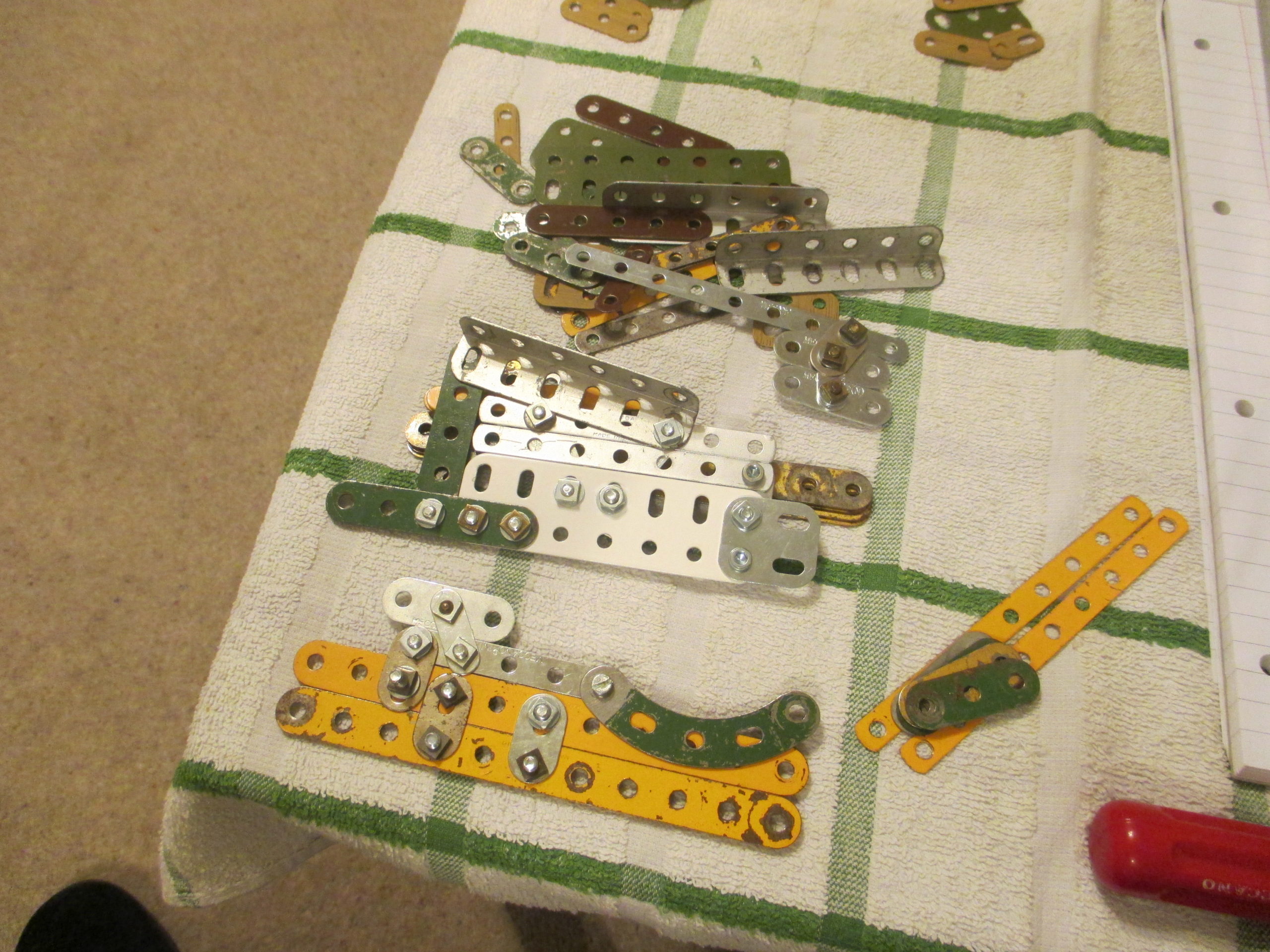
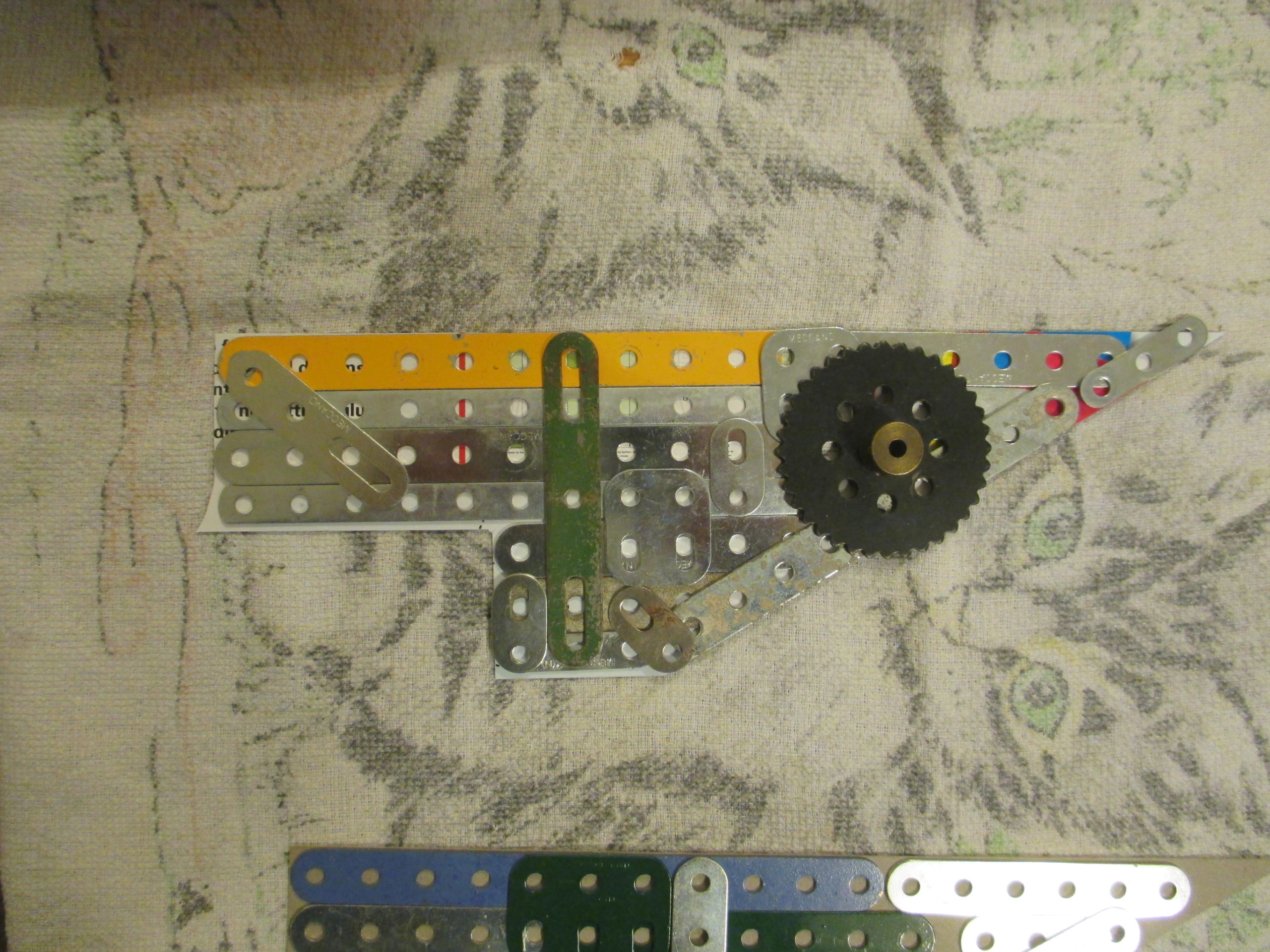
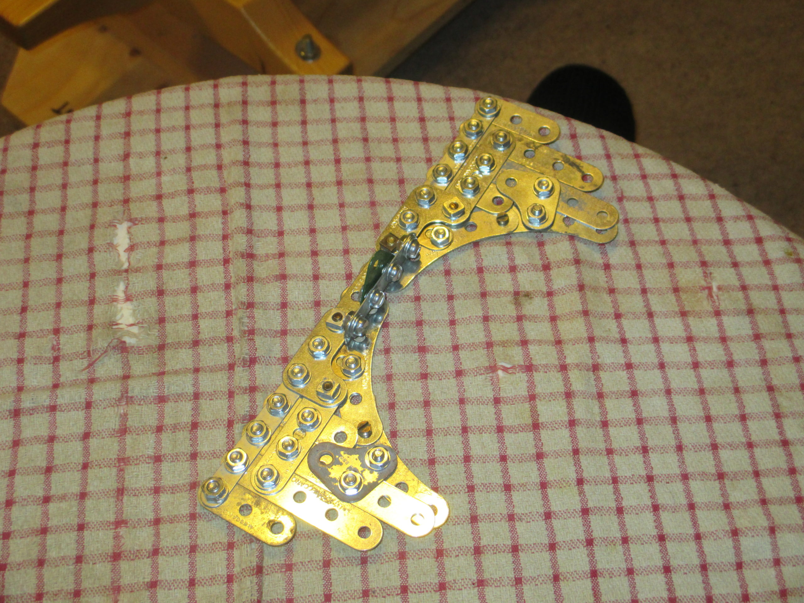
At this point in the build I was effectively building everything twice; once for prototyping (how it could be done and what parts were needed) in scrap or unprepared parts, and a second time in fully painted parts. This is why I took so many pictures from this point, to remind me how to assemble the parts after painting.
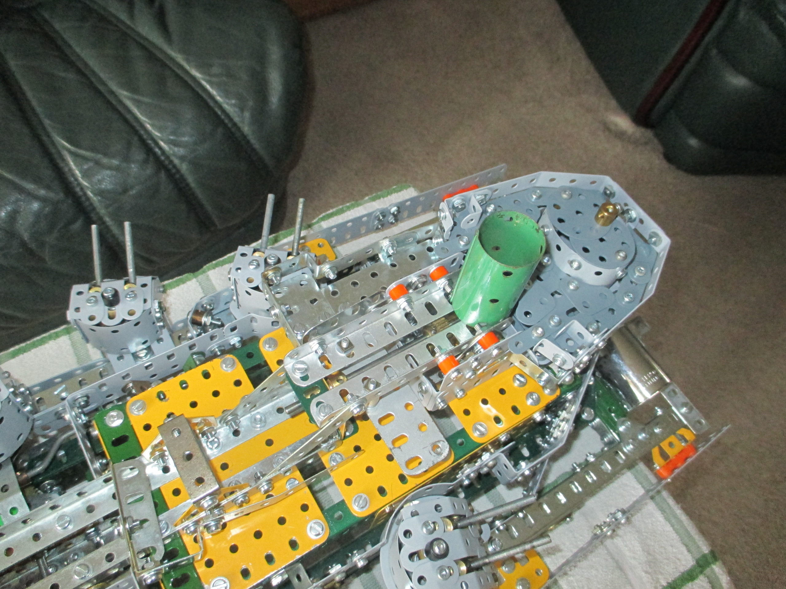
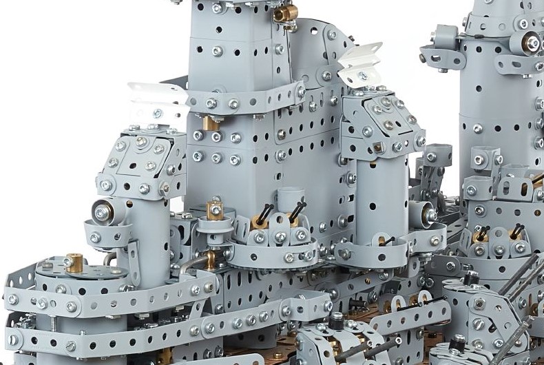
The superstructure colour is the authentic grey, but not ‘battleship grey’! Originally, I bought some battleship grey spray cans and sprayed some test pieces, but these looked far too dark compared to the internet photos. Further research revealed that US warships were painted in ‘Haze Grey’, the equivalent of UK’s ‘Window Grey’. The RAL number for this is 7040, so I bought seven 400ml cans of semi-gloss from Express Paints for the job. The darker battleship grey was used for the un-wooded deck areas and main turret roofs as seen on the real ship.
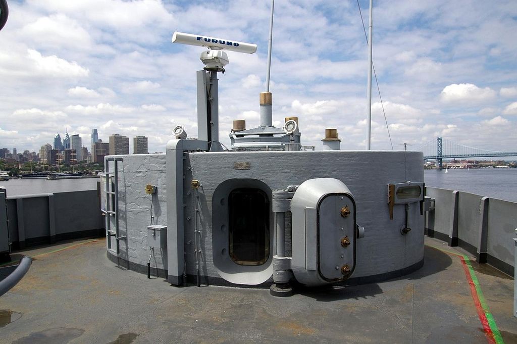
The real ship’s conning tower extends down three stories, giving protected access to other levels of the ship. The ship could be totally controlled from within it, and it is immensely strong. The walls of the tower are 17 inch thick steel.
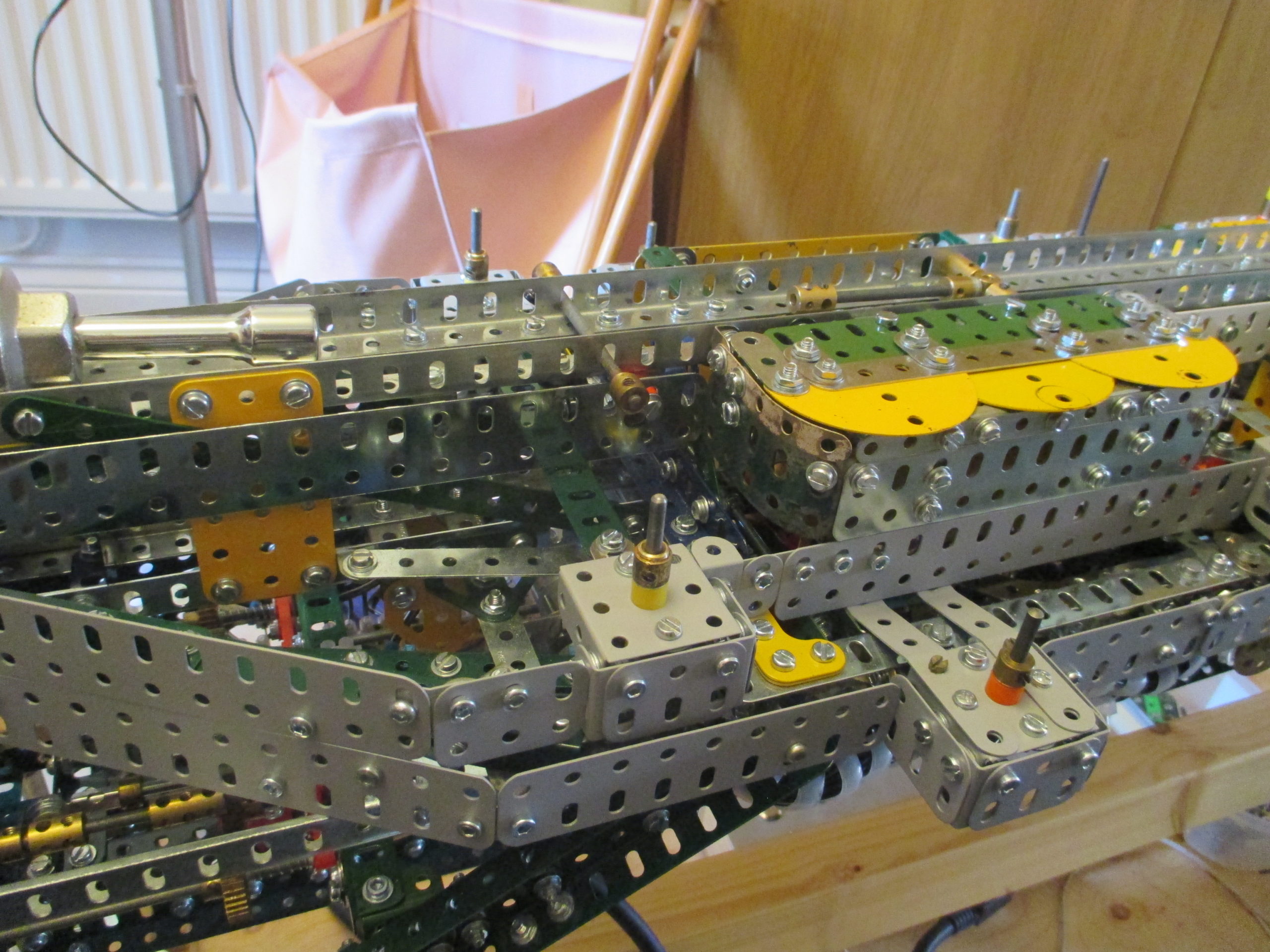
The outer shell of the superstructure is decorative (non-load bearing) which allowed freedom to add and remove without affecting anything else. Each deck sidewall is mostly done with flat girders, with only a few needing to be bent into shape.
At this scale, each deck height should be less than one inch, but a flat girder is wider than an inch. It was not possible to ‘lose’ all the extra height for each deck, so there is an accumulated error making the superstructure a little higher than it should be.
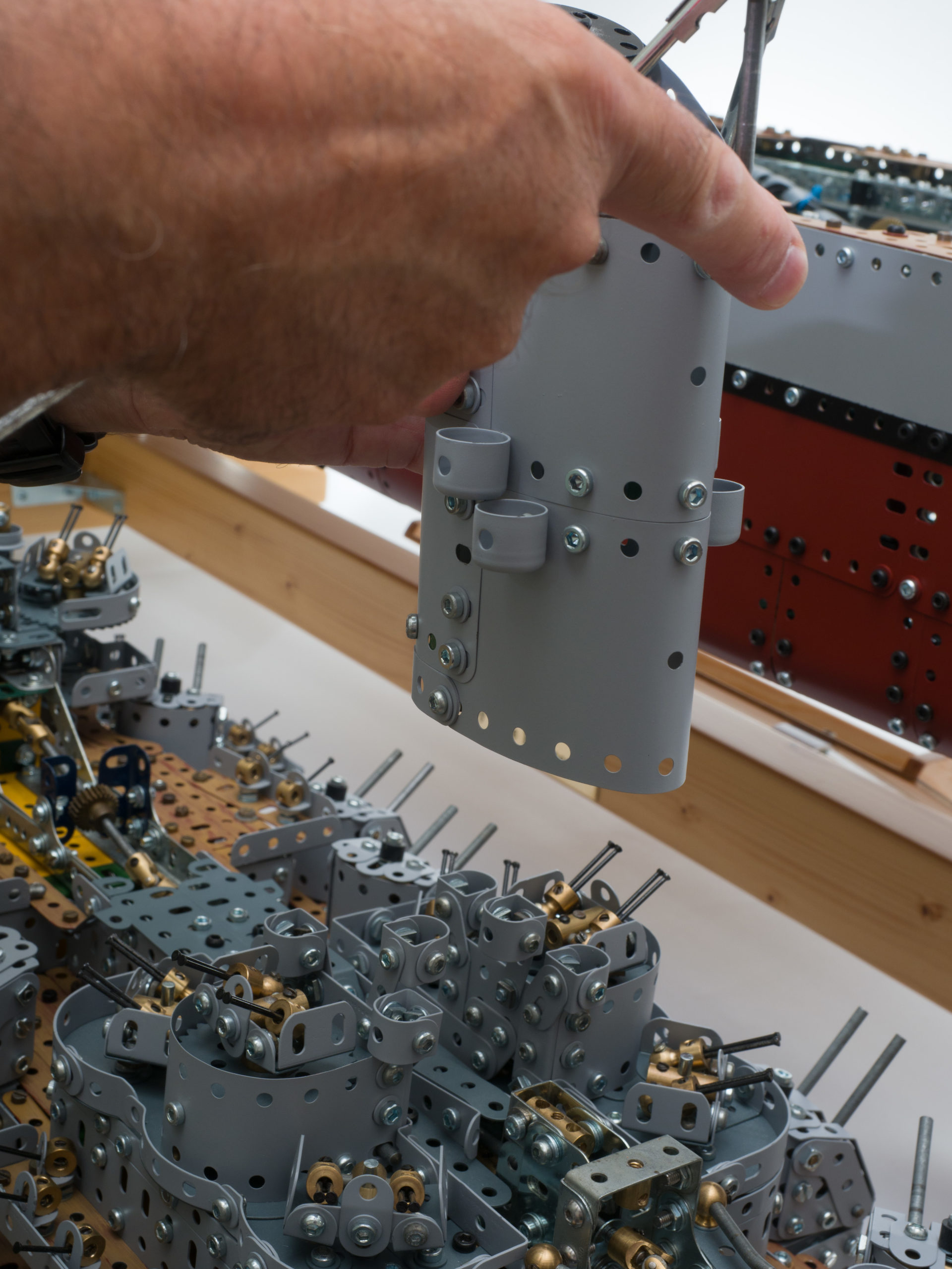
The tallest part of the superstructure also incorporates the forward funnel, two of the gun director radars, and the forward lifting handle masquerading as a radar boom. This was built as a separate module, detachable from the structure.
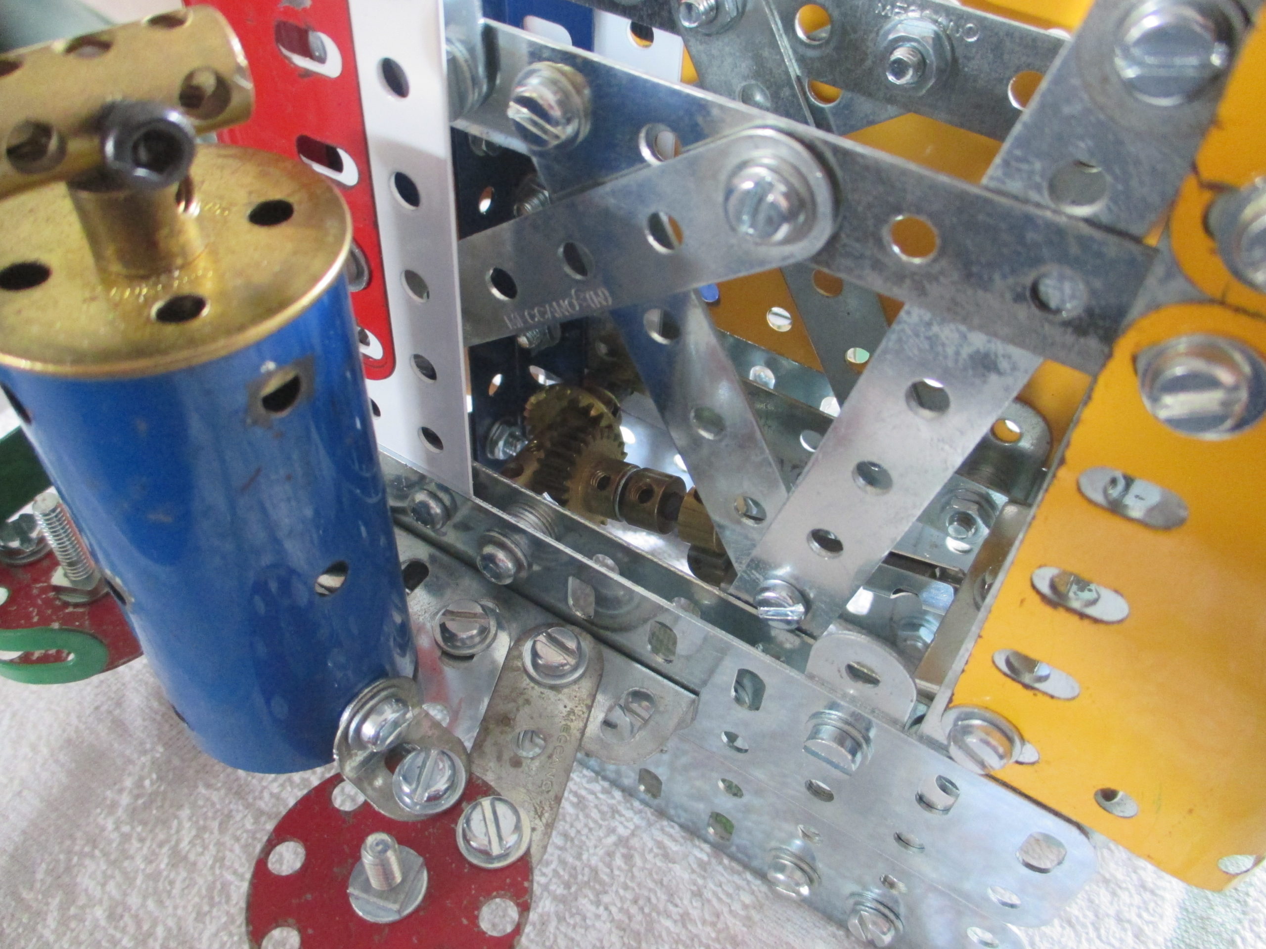
The load path down from the boom is quite robust, and connects to the structure using three rods.
The ends of the rods are just visible and are slid into place through aligned holes (not only the slotted holes of the flat girders).
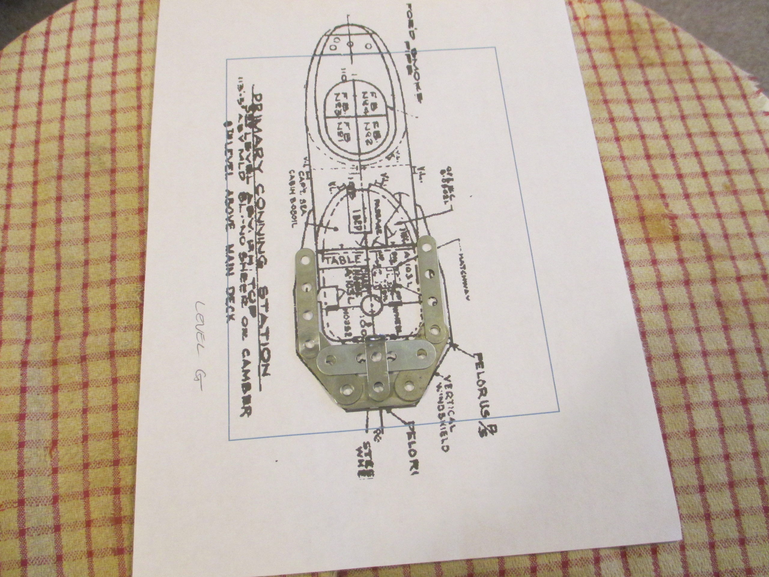
The scaled up blueprints were used to achieve the right shapes for each deck level.
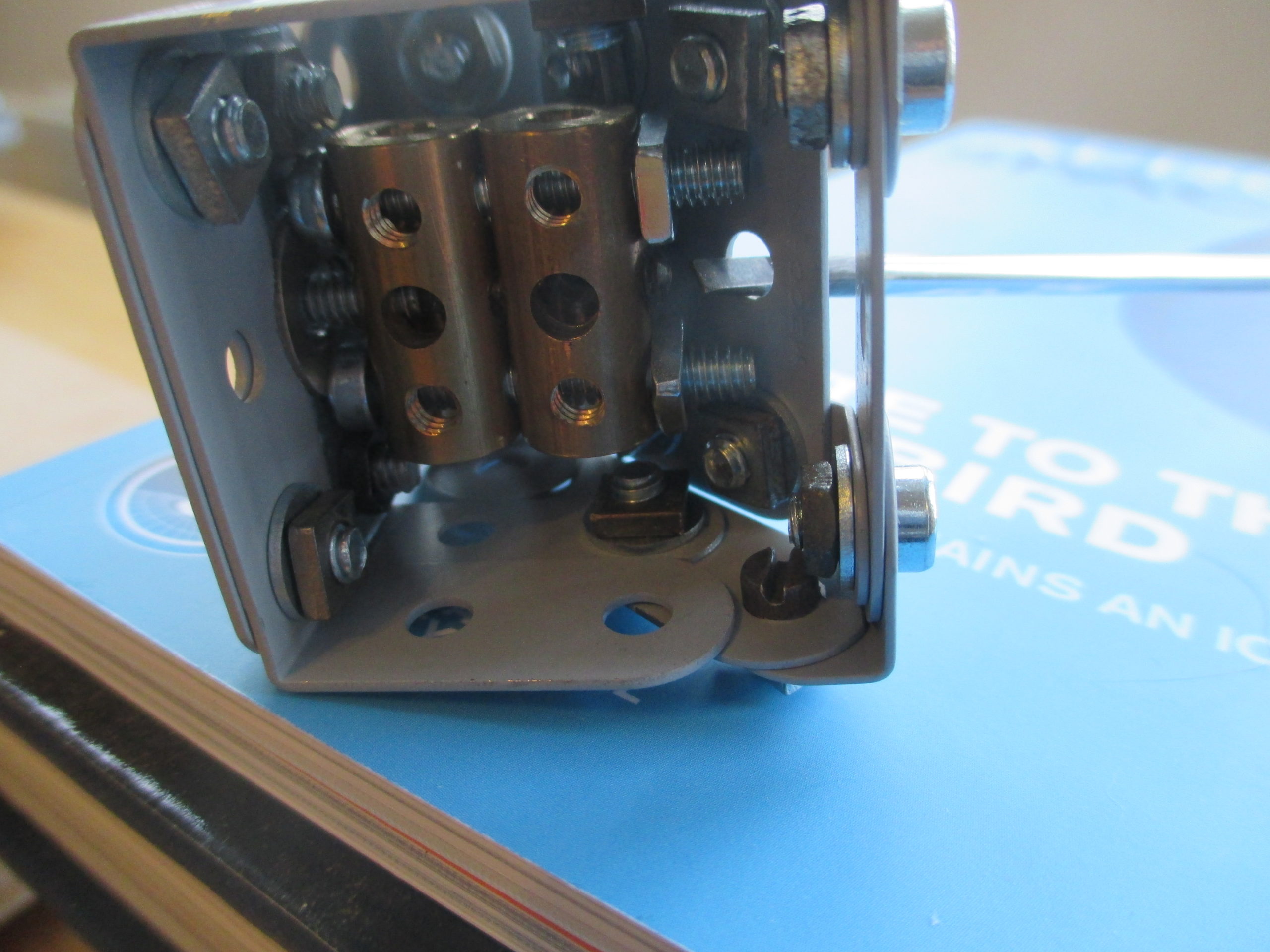
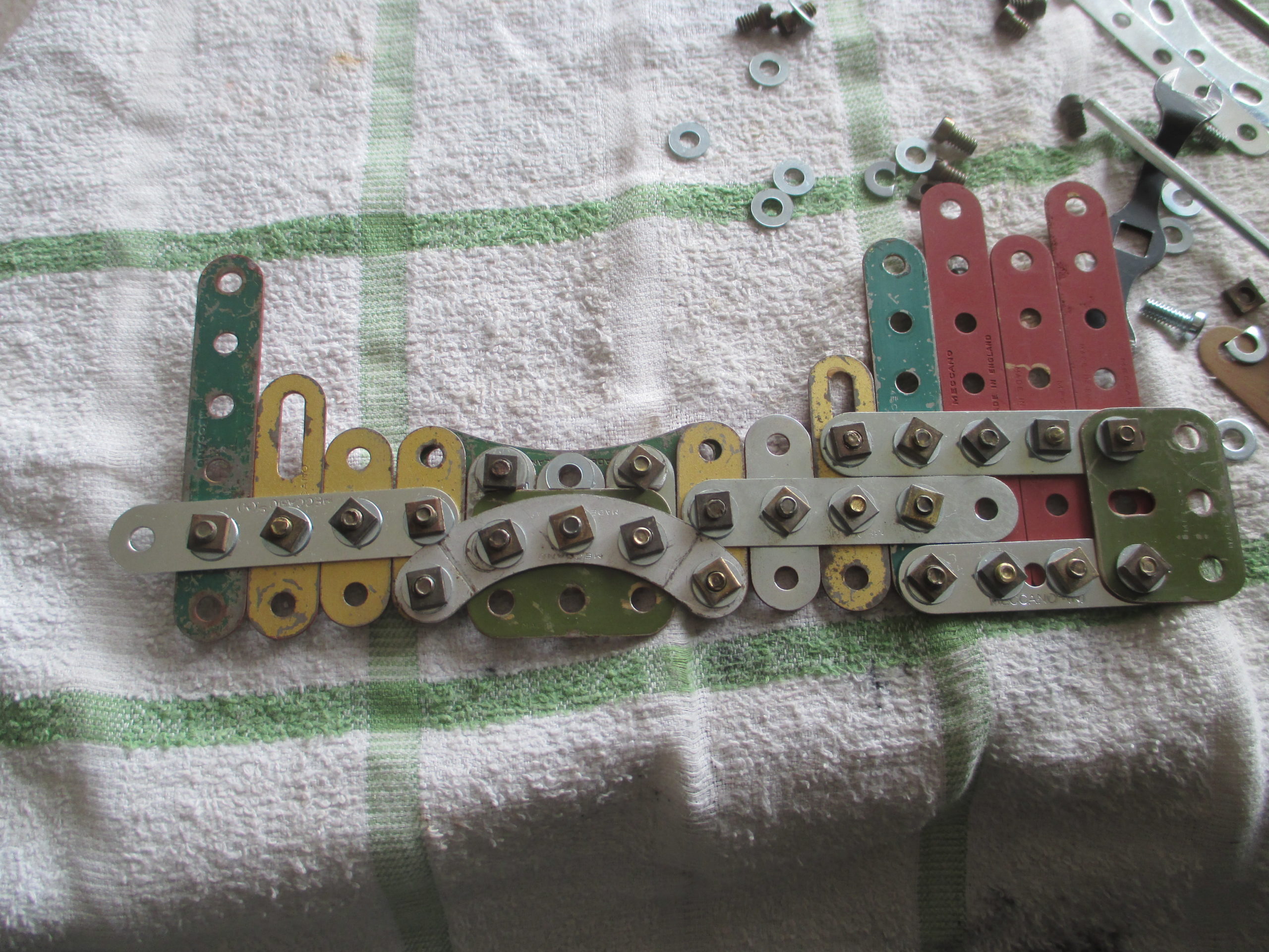
Many of the joins for the flexible plating are over curved profiles, some quite tight curves. Using a nut and washer on the inside of the curve would distort and flatten the curve locally and spoil the profile. However, Meccano hex nuts have one face slightly domed, presumably due to their manufacturing process. Without a washer under it, this allows it to be tightened inside a curved profile without distortion, but only if it is against a hole, not a slot. For slotted holes and tighter curves, a collar or coupling is used.
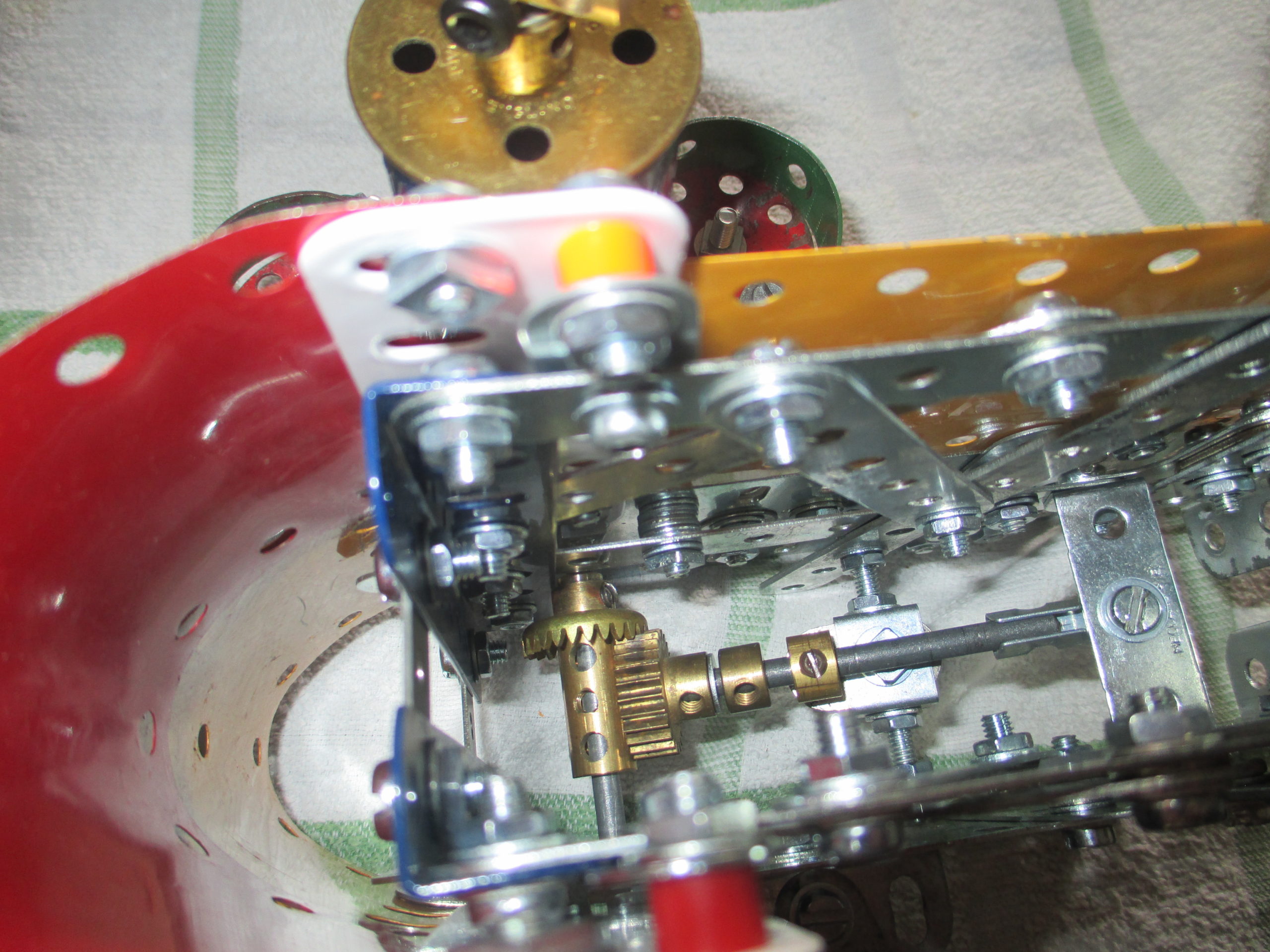
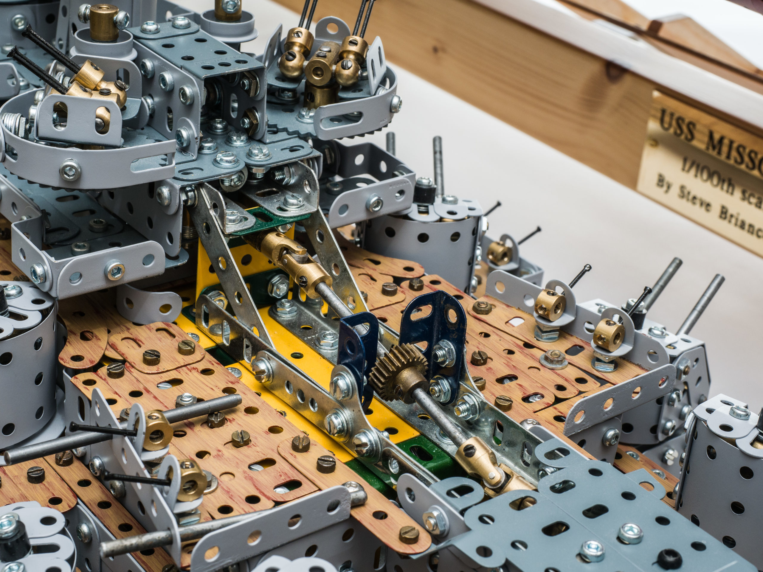
The drive for the two gun director radars enters the module via a 25 tooth pinion, which engages with a similarly angled pinion below it when the module is lowered into position.
The drive below the module continues forward to operate the forward radar. Atop the module are the antennae, and a circular radar ‘dish’ formed from narrow strips painted white.
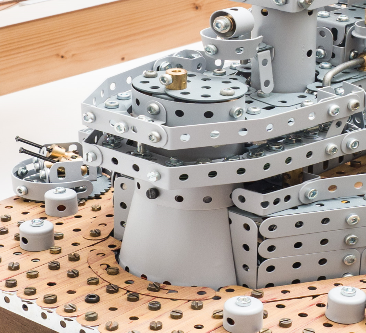
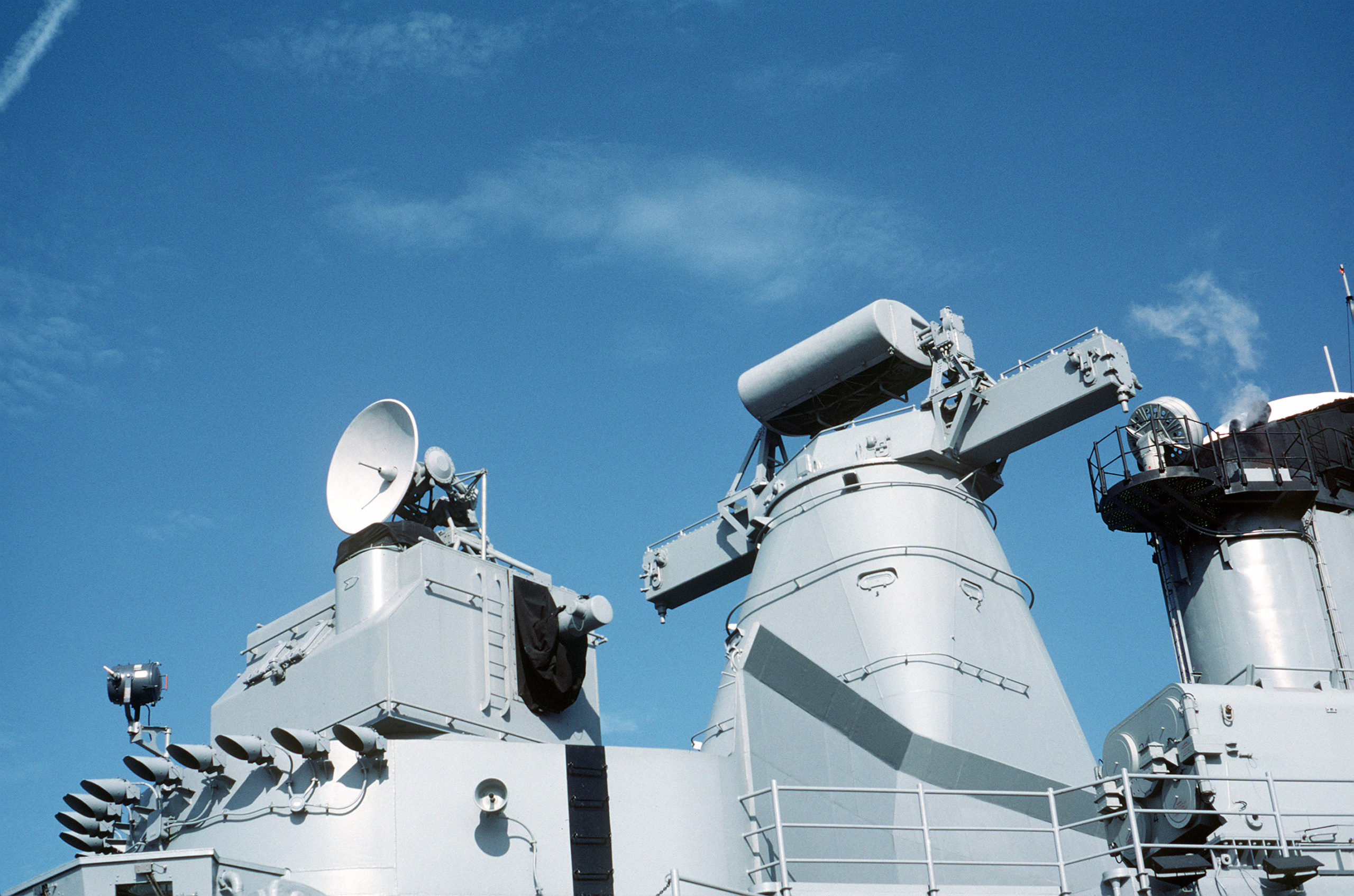
The gun director radars have an antenna formed from a 1½ inch square flexible plate, folded in the manner of the real thing.
A flexible 1½ square doesn’t exist in Meccano, so a cut-down 1½ x 2½ was used, because the rigid type would not bend so readily. The radars are mounted on 1¼ inch diameter cylinders, which actually raises them higher than they should be, but were convenient in other respects.
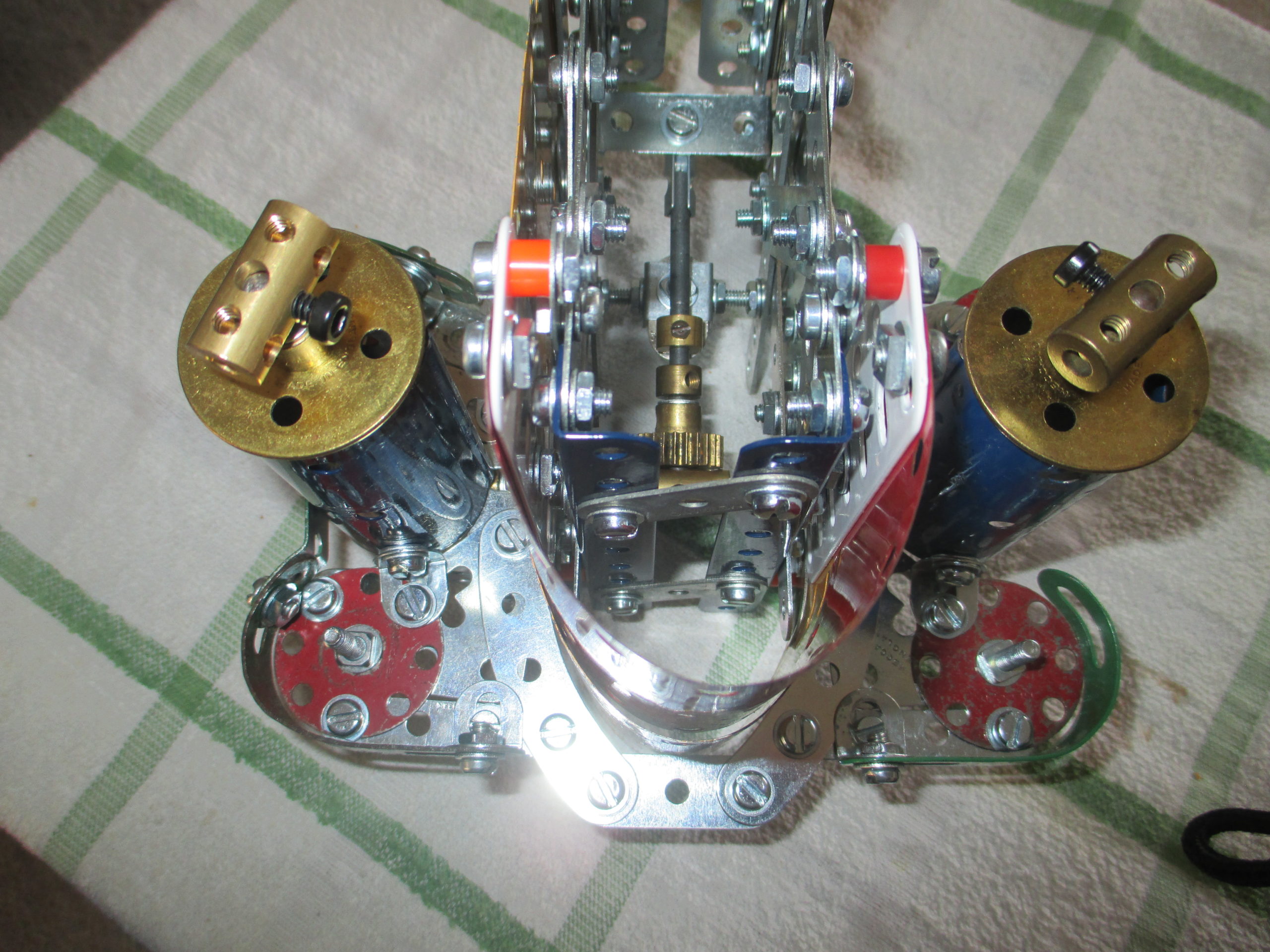
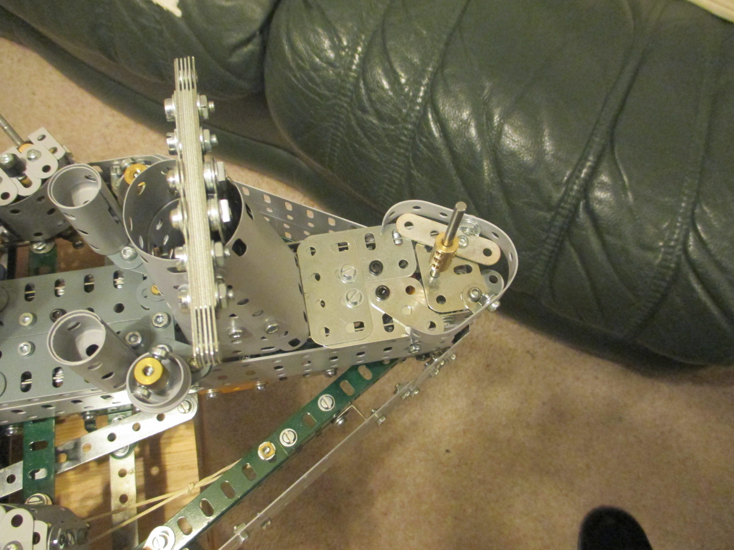
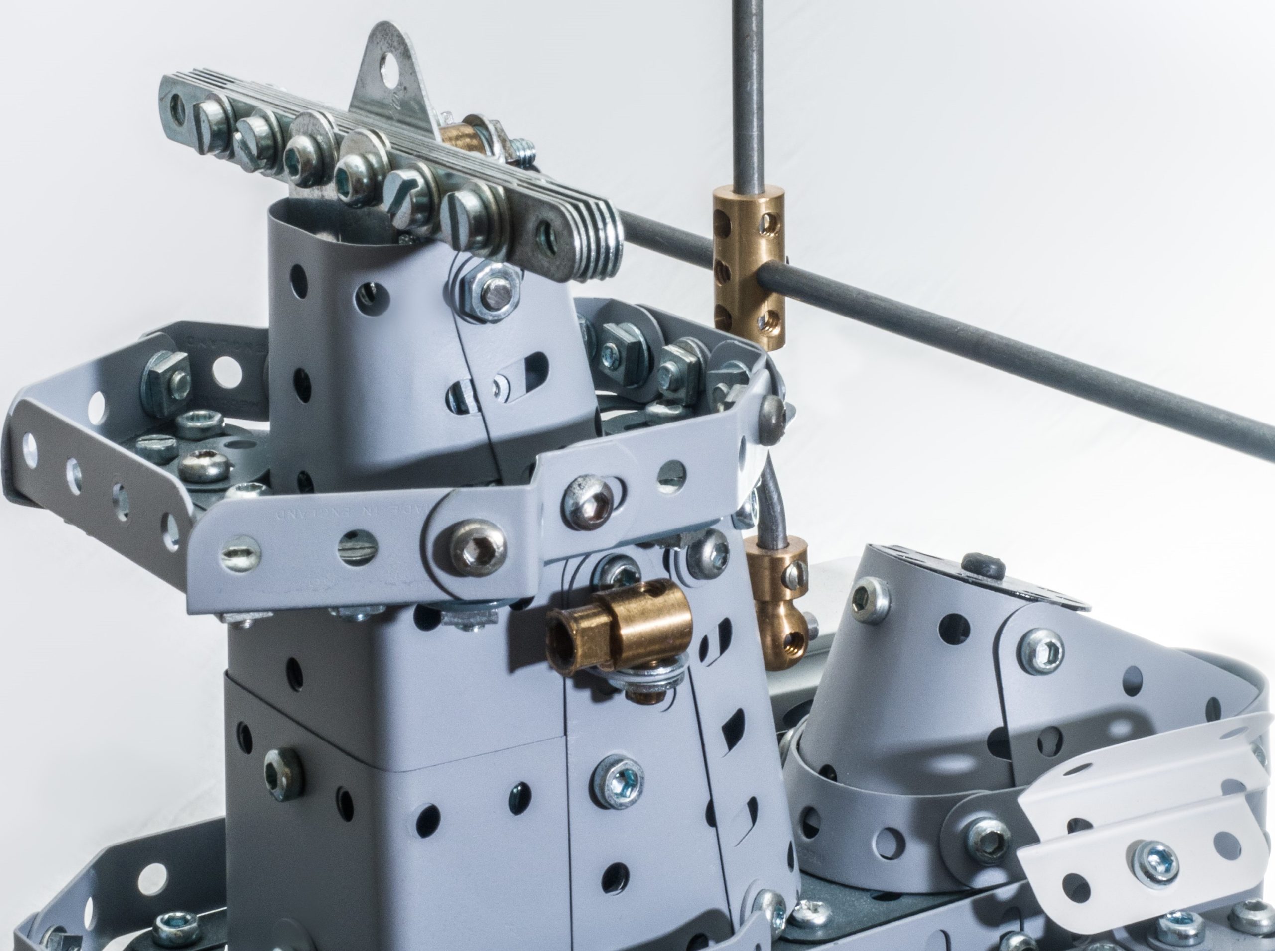
The aft gun director radar was not mounted on such a 1¼ inch cylinder as the height would look wrong relative to the radar boom tower just in front of it. Instead, 2½ x 1½ flex plates have been tightly curved around and joined inside using couplings. One of these couplings also mounts the angle bracket for securing the assembly, and holds a vertical rod which passes through the flanged wheel to anchor it against rotation.
Unlike the other gun director radars which incorporate the central drive rod, this rod is not part of the radar assembly. Its difficult connection to the drive mechanism, and very limited access within the superstructure precluded this. So a different means to connect the radar head to the rod is used, whilst still giving access to the securing grub screw. The tip of the screwdriver is just visible in the photo.
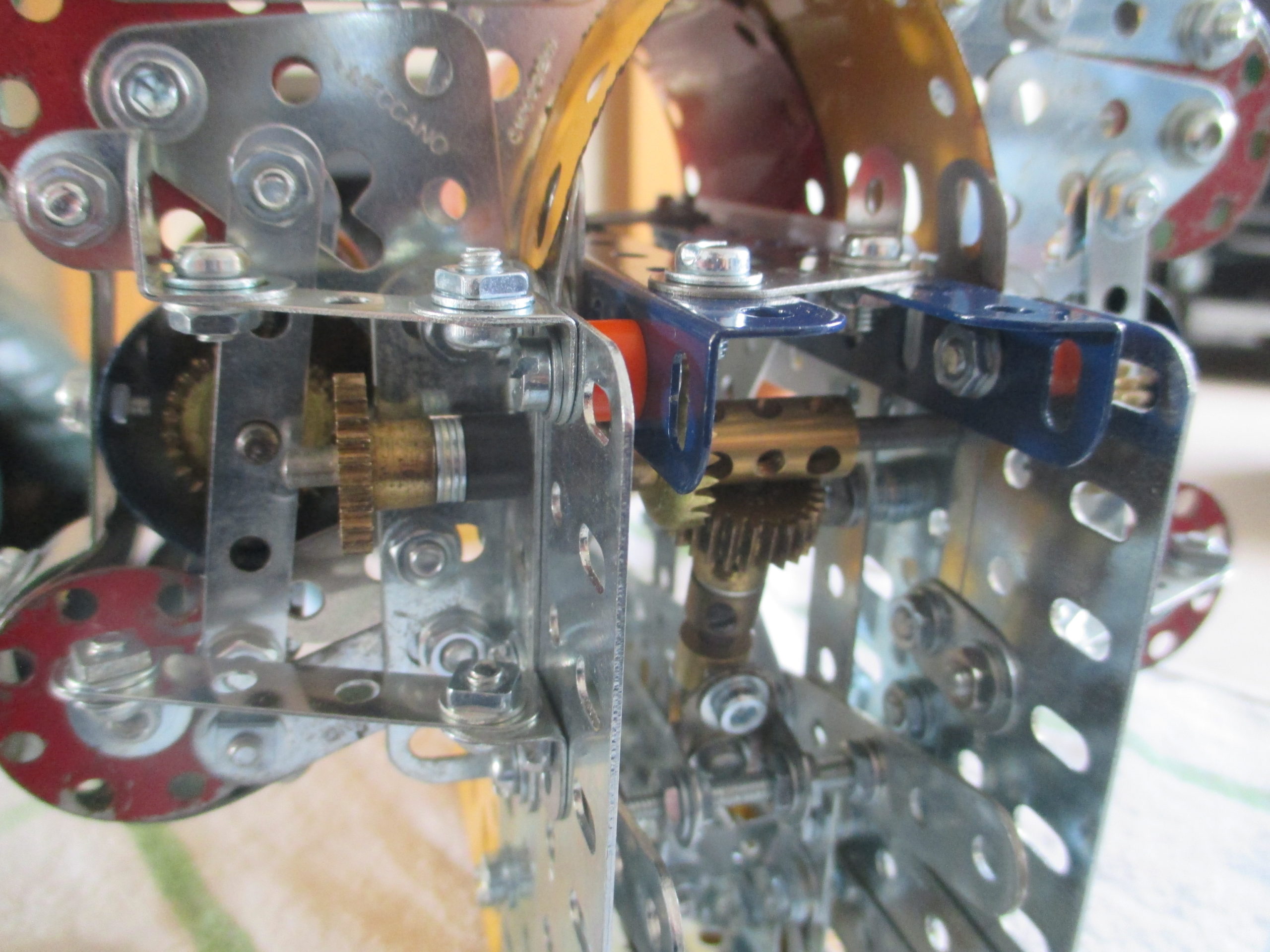
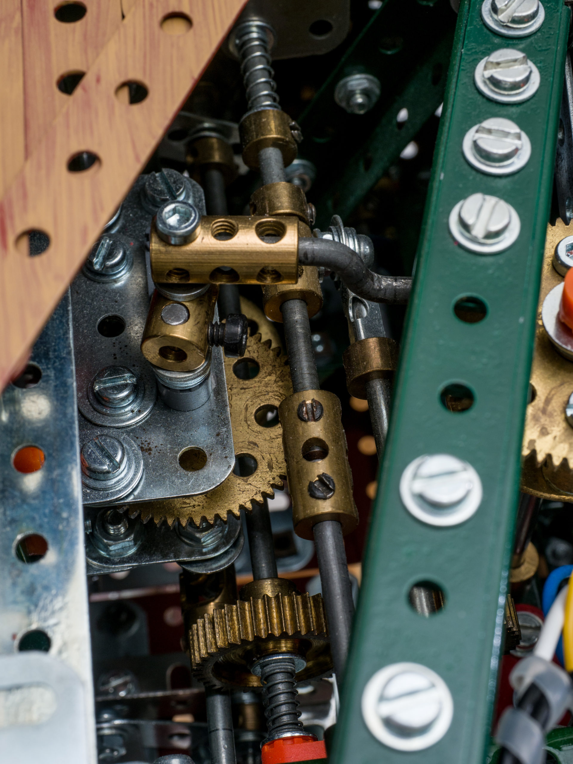
The drive for all four gun director radars enters the superstructure from below, near its aft end. Another pair of mating contrate gears engage when the superstructure is lowered into place.
A motor in the centre section drives a ‘short coupling’ crank which gives an oscillating motion to the contrate gear. The motor and its gear train are built as a removable module.
Inside the superstructure the driveshaft extends aft to the rear radar, and forward to the other radars, taking a central route over the top of all other mechanisms.
The aft funnel is also a removable module, but without the need for a robust attachment.
It is removed by undoing a single allen head bolt down the middle of the funnel.
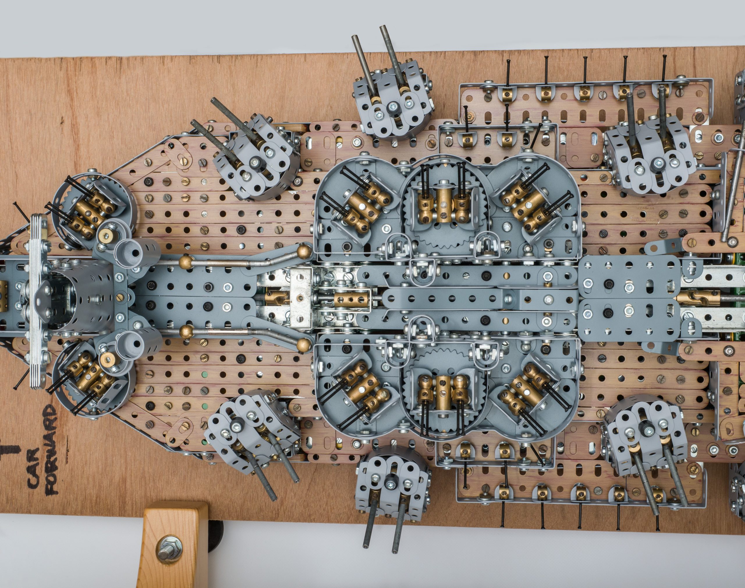
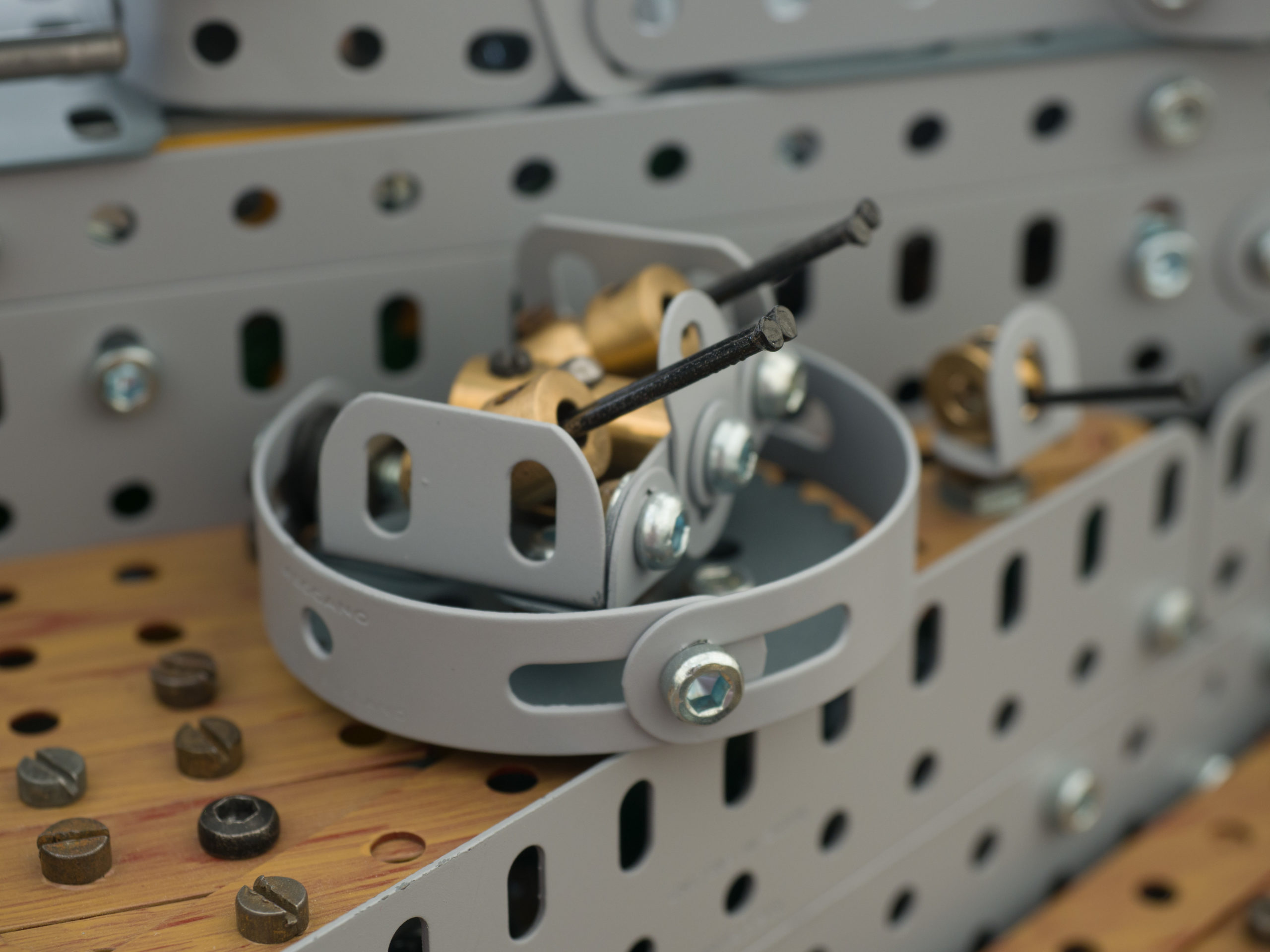
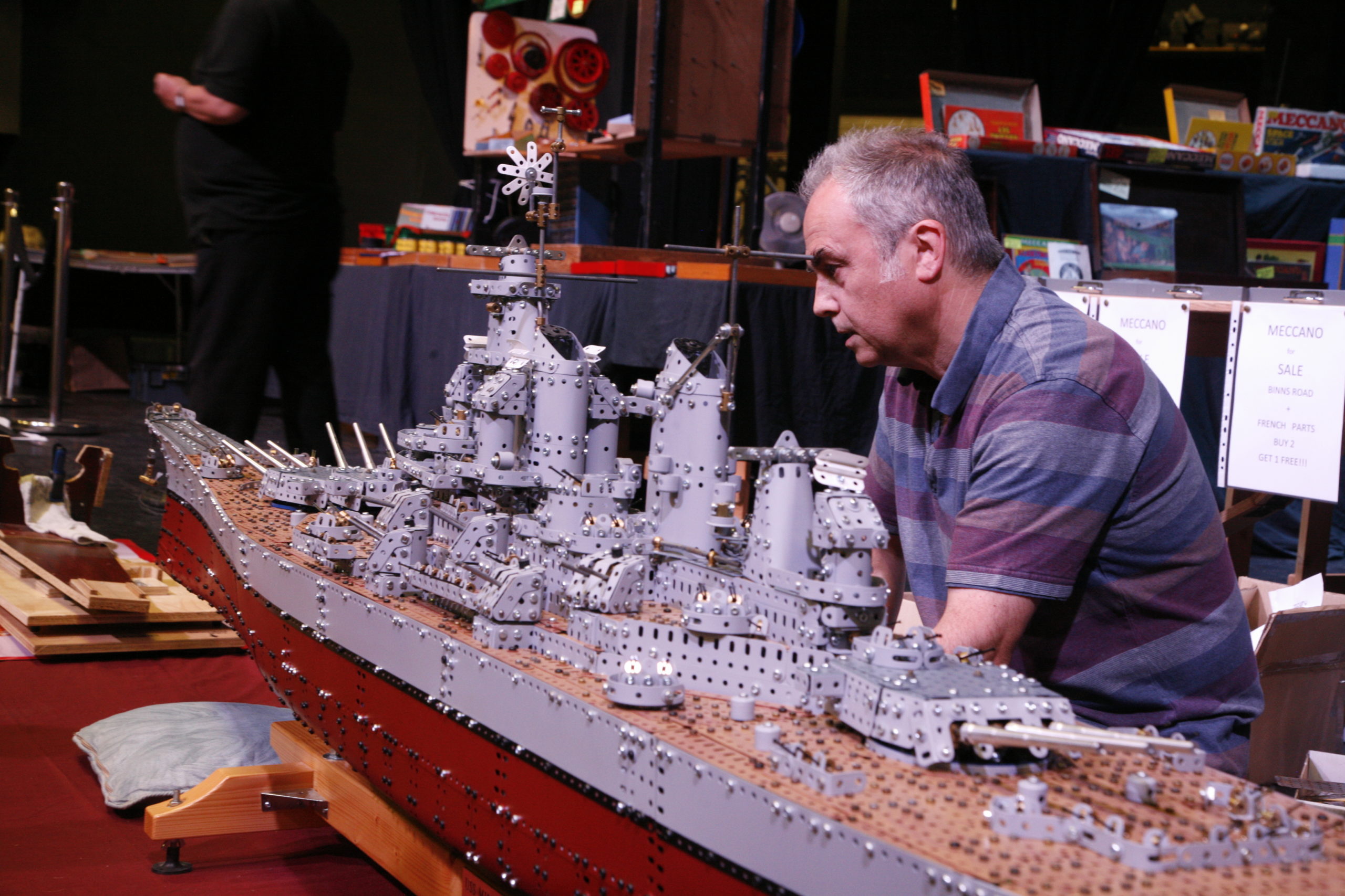
Between the funnels are six Bofors gun installations. The ship has twenty such installations - each with four guns – twelve of which are on the superstructure.
The action photo of these guns was taken moments before a Kamikaze plane struck (seen top left of photo).
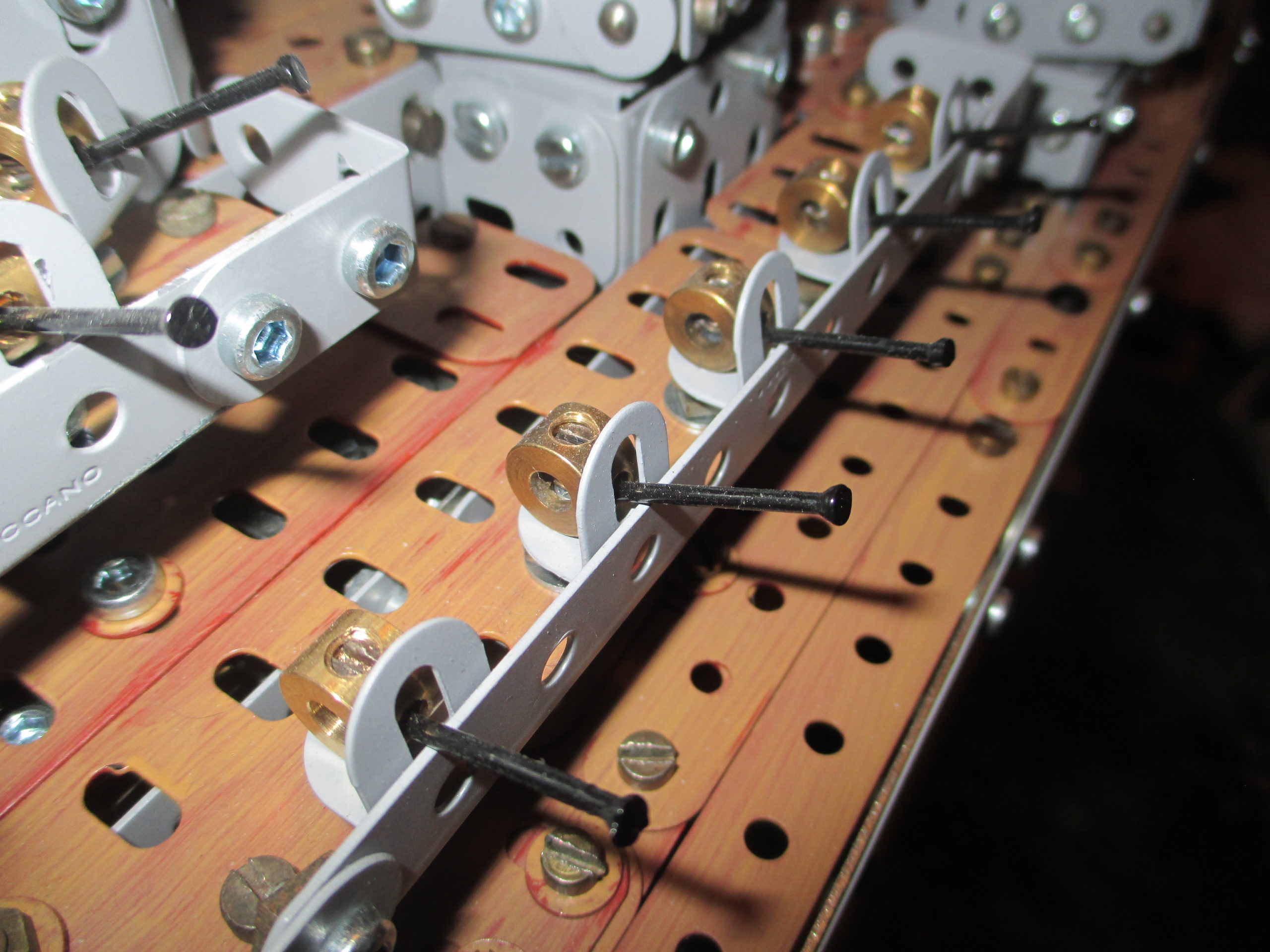
There is no Meccano component at this scale to represent the guns, so panel pins sprayed black have been used. Their flared ends give the appearance of a barrel even though Bofors guns didn’t have this feature.
Each pair of pins is inserted into a handrail coupling, with grub screws in both top and bottom holes. When the grub screws are tightened equally, their tapered noses force the pins apart and up against the sides of the hole, thus keeping them positioned firmly.
The base of each installation is a 2 inch sprocket, chosen for convenience of diameter, and painted in the darker battleship grey.
The aft lifting handle masquerades as another radar boom, and is of similar construction to the forward lifting handle. But in this instance it is not detachable from the structure.
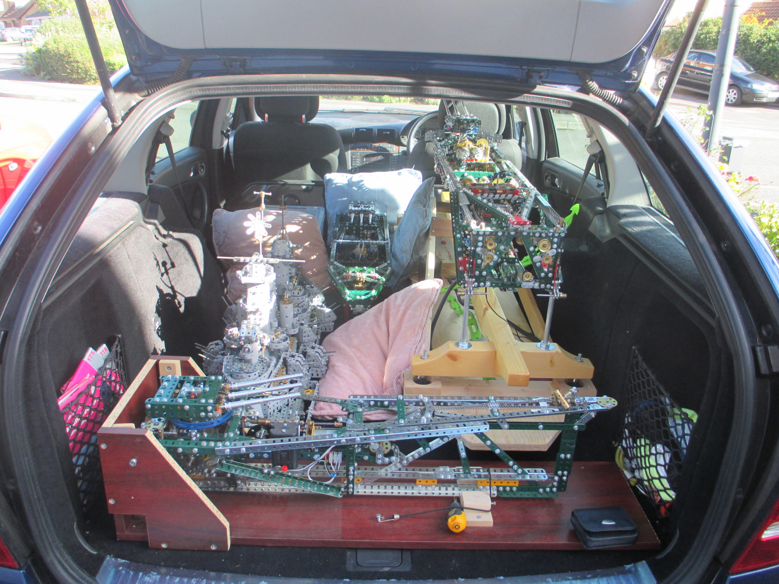
By now, transporting the model to meetings and a few exhibitions was becoming difficult. Firstly, fitting it into the car without the sections damaging each other, and secondly the physical effort in getting it in and out of the car.
Lifting the centre section on its stand is a two person job, and often the only other available pair of hands is my wife, which eventually became too much for her.
Lastly, I was finding a few nuts/bolts/washers on the car floor when unloading. They could have been the loose ones dropped into the model during build (many, many times) and shaken free by the journey vibration. Or they could have been vibrated loose and come adrift; I still don’t know. Eventually the numbers found diminished – currently to zero.
With all the systems and features in place, the superstructure decking came next. The individual areas of decking were prototyped with unprepared parts.
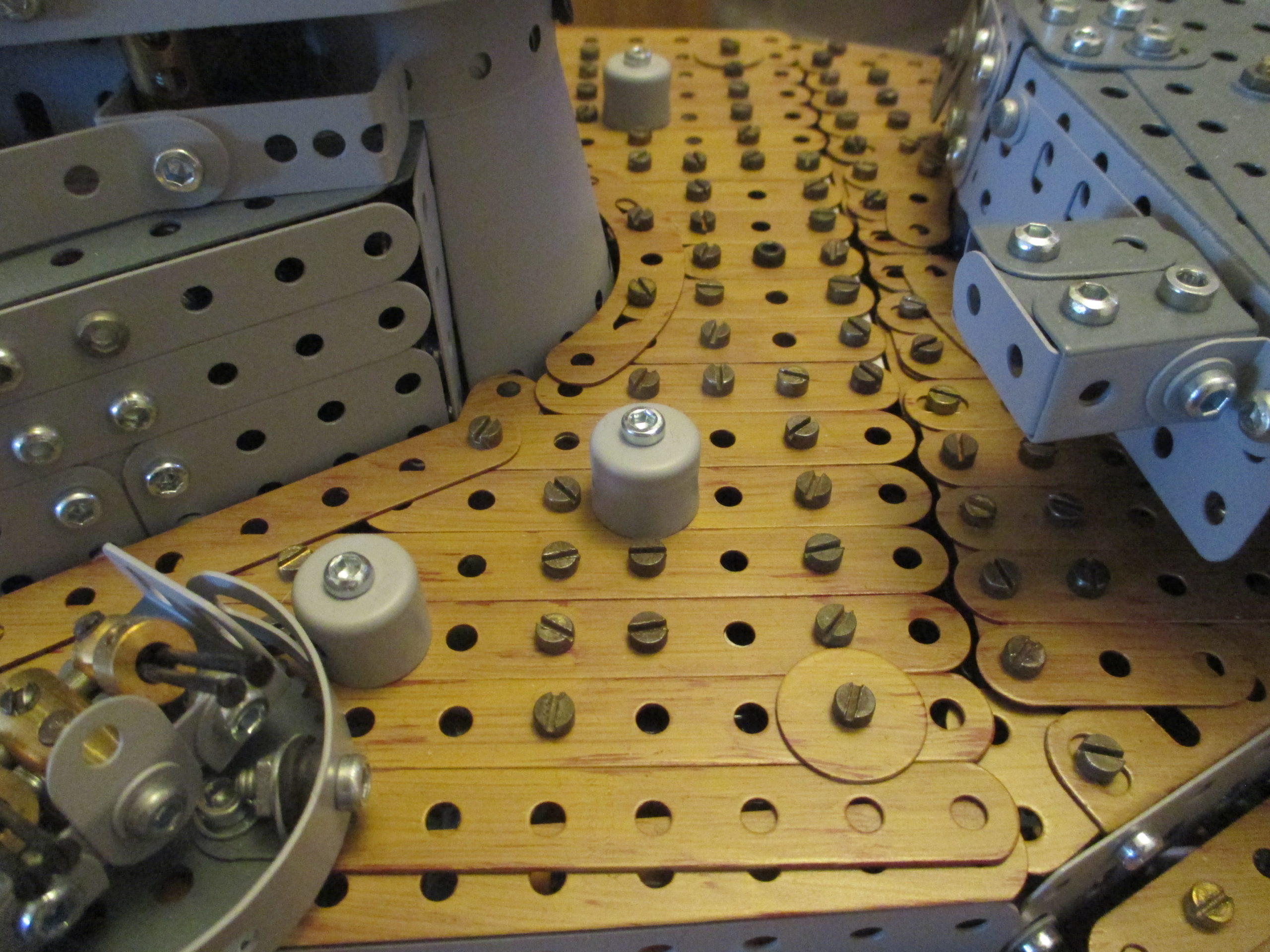
I experimented with a few ‘woody’ coloured paints, but they all looked naff. Instead, a three step process was used to achieve a wood grain effect. Firstly, the prepared parts were sprayed with a red oxide primer. Then some tan coloured emulsion (from the B&Q mixing desk) was applied very sparingly using a small stiff haired brush, stroking in the direction of the wood grain.
Where a part needed to be set at an angle, it was laid onto the paper at that approximate angle but still painted ‘up and down’. The resulting streaking allowed the red paint to show through giving the effect of wood grain. Finally, it was oversprayed with clear satin varnish to protect it, as the emulsion was very easy to scratch off with the slightest touch. The end result is a very pleasing wood effect.
Slotted Meccano bolts (no washers) are used for decking assemblies as they look better with the wood finish. If the bolt is through a slotted hole then a washer has been used, but painted in the same wood effect manner.
Each deck panel assembly is secured down by two or more bolts into captive nuts (either couplings, threaded bosses, or sometimes collars on rods). For this, black allen head bolts are used for identification of their location.
The decking has deliberately been done using strips rather than larger plates, to give the illusion of planking. It also allowed for much finer matching to the deck contours. Some of the deck panels are quite large, thus many strips wide.
Because of the tolerances on the width of a strip, it is not possible to secure many to a ‘cross strip’ before the holes no longer line up for a bolt to pass through. I found that a maximum of five adjacent strips can be secured this way. To overcome this limitation, the underside of wide deck panels are supported by staggered cross bracing, and slotted hole strips.
A few deck locations are too narrow even for a single narrow strip, so a stack of strips edge on have been clamped and painted instead.
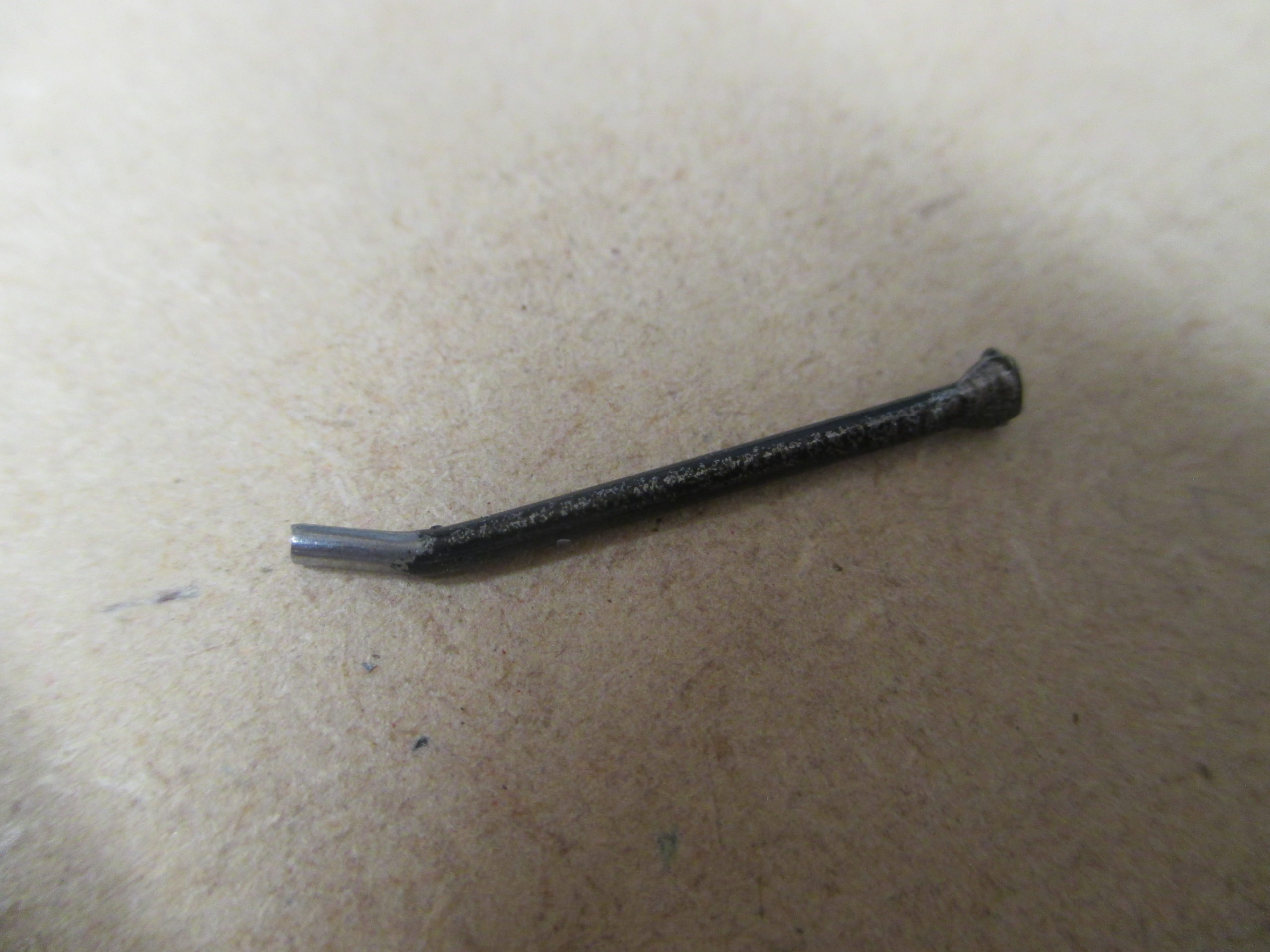
The many single machine guns also use painted panel pins, with the tail ends flattened and bent.
The tail end passes through a four hole collar, and a grub screw tightens down onto the flat. The gun is then screwed down over the bracket posing as a shield onto the protruding tail of a long bolt.
There are some additional details that probably go unnoticed, such as the two ship’s bells, ship’s horn and spotlights.
Of all the ship’s systems, the 10 smaller gun turrets have been the most troublesome. Most of the issues have been due to the high driving torque causing shaft slippage. This has largely been overcome by filing local flats on the majority of the shafts. Where possible, slotted screws tighten onto these (slot heads allow for greater tightening), or grub screws with their tails filed flat. Despite this, part of the system still failed to move during the first day of Skegex 2019.
After an hour’s investigation it turned out not to be a failure of the mechanism, but a minute particle of swarf or grit that had found its way into the fine clearance between a layshaft and its brass bearing causing it to seize. Once cleared and oiled, it functioned fine non-stop for the remainder of the exhibition. So despite mitigating against predictable problems, there is always the unexpected!
