The Hull
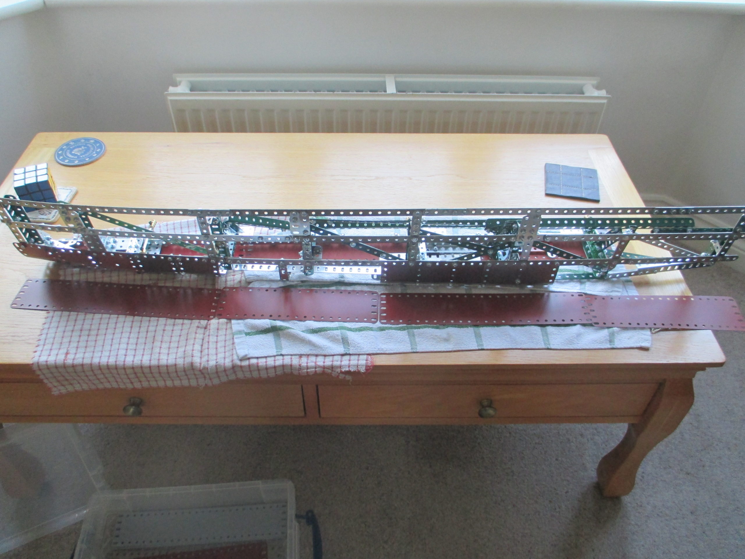
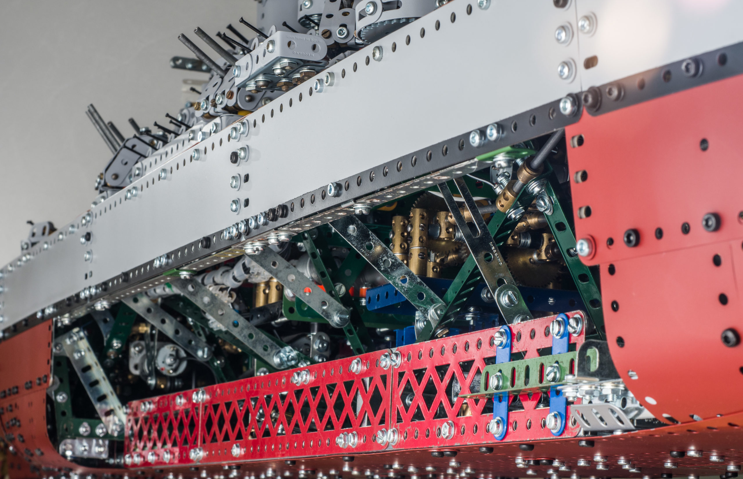
Having a full hull model means covering over all the innards, which must still be accessible for maintenance. The plan was therefore to have detachable sides on the centre section. They also had to be quickly detachable for the dozens of times they would be on and off during construction, and later during exhibitions if problems arose.
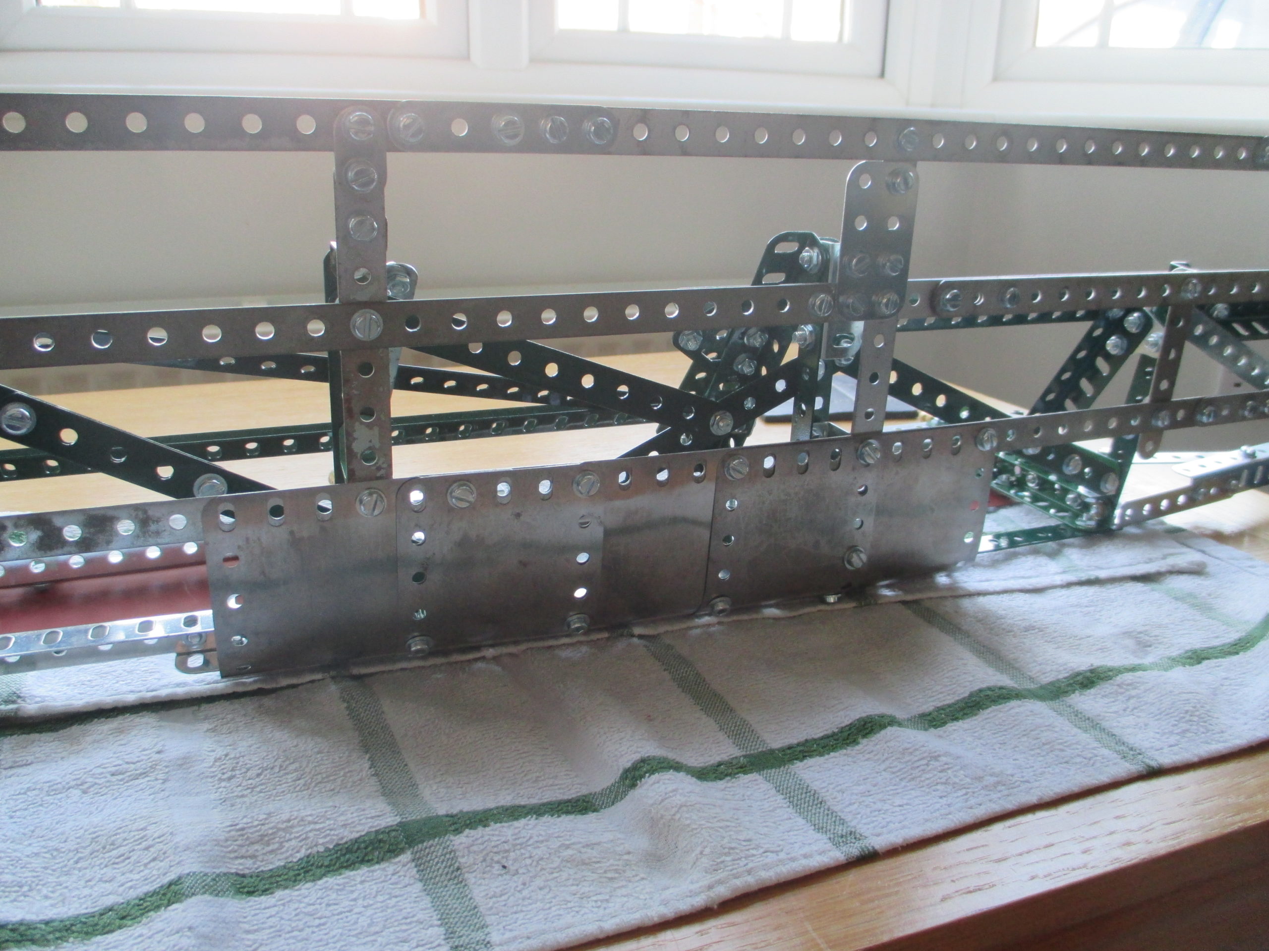
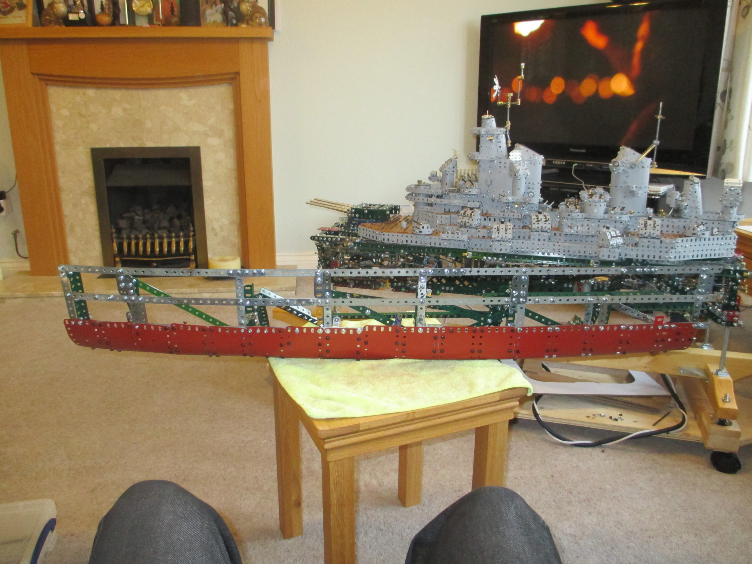
The solution to this was to build each side as a separate module on their own frameworks, and hinge them such that they can be lowered down to allow access or slid off the hinges entirely.
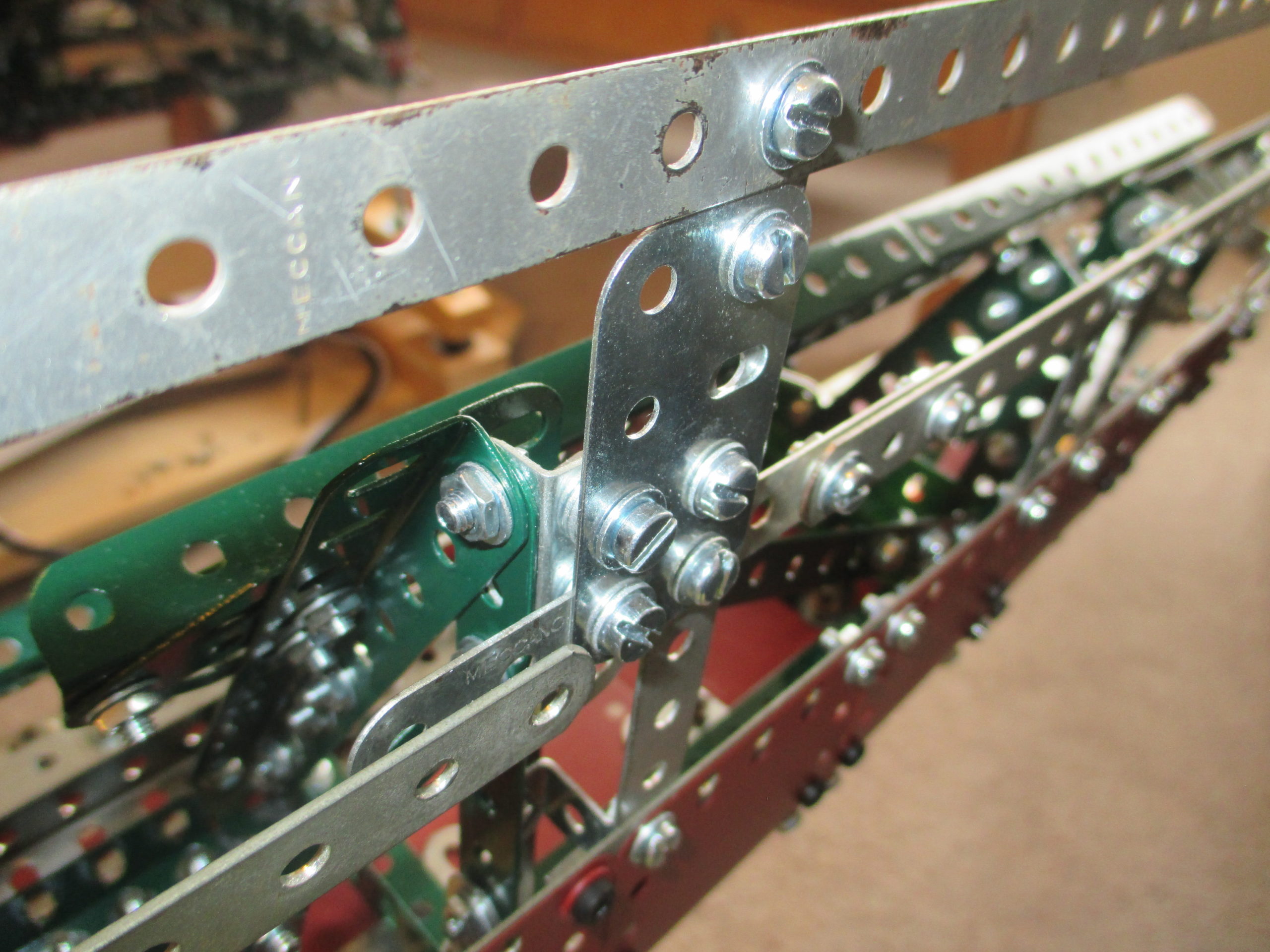
In the end, just lowering the sides down wasn’t possible, and each side can only be hinged down a little before being removed. The reasons will be evident later. Each framework is fairly rigid, but additional rigidity comes from the cladding itself due to its curvature. The framework does look somewhat unsightly, but needed to be clear of all the model’s innards so space was limited.
The hinge line for each side obviously had to be within the hull profile, else bits of the hinges would be sticking out spoiling the clean underside. Also, the hinges needed to be directly attached to the keel for rigidity.
These constraints mean the hinge line is about ½ inch above the bottom surface of the hull, and set either side of the centreline. From a geometry perspective, this results in the lower edge of the side panel moving inboard as well as down during lowering. This limits the amount it can hinge down before clashing with the keel.
The lower face of the keel itself, initially intended to be the hull’s ‘inner skin line’, was not appropriate for this as it is green and open-faced apart from the occasional capping plate.
Unfortunately this meant the hull sections provided in the blueprints – when scaled up – would not be deep enough to work from for creating the hull profile. So a set of sections ‘adjusted for hull depth’ were produced by stretching the blueprint image vertically a little to account for the extra depth. This is something I should have foreseen at the beginning and accounted for in the depth of the internal structure.
The keel plates are 2 1/2 wide, fitted close to the underside of the keel. Modern plastic Meccano strips are used as spacers, so the plates are just clear of the keel bolt heads.
Rigid plates were used because I thought there may come a time when I needed to lift the centre section off its three supports using wide straps. Flexible plates would buckle under the load.
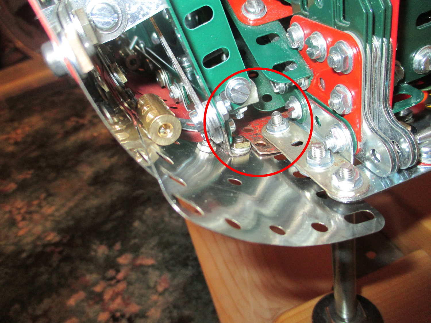
This arrangement means the hinge line is not only above the keel, but also somewhat inboard of the join line between side panel and keel plates. Therefore that part of the hinge on the side panel overhangs the edge of the panel by some way.
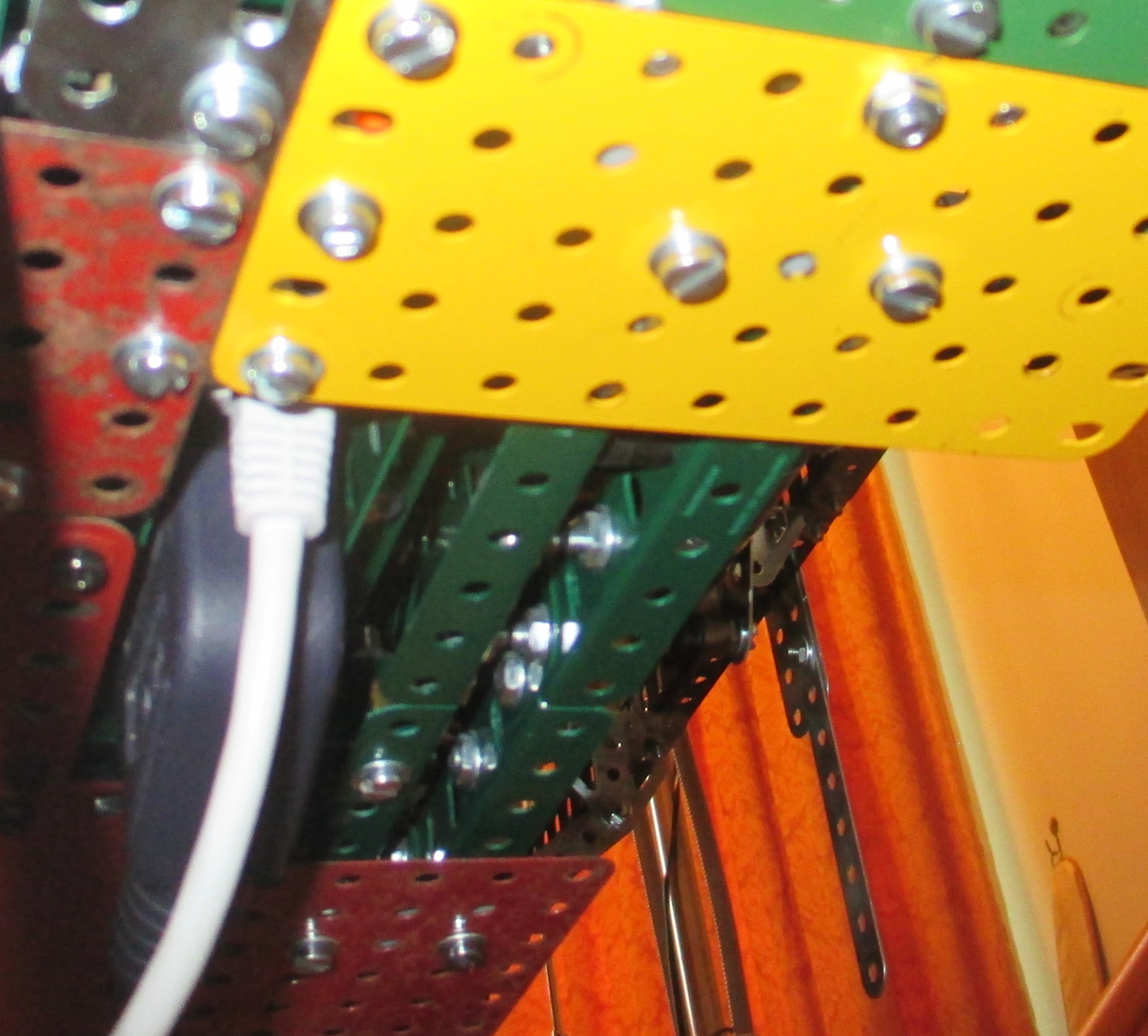
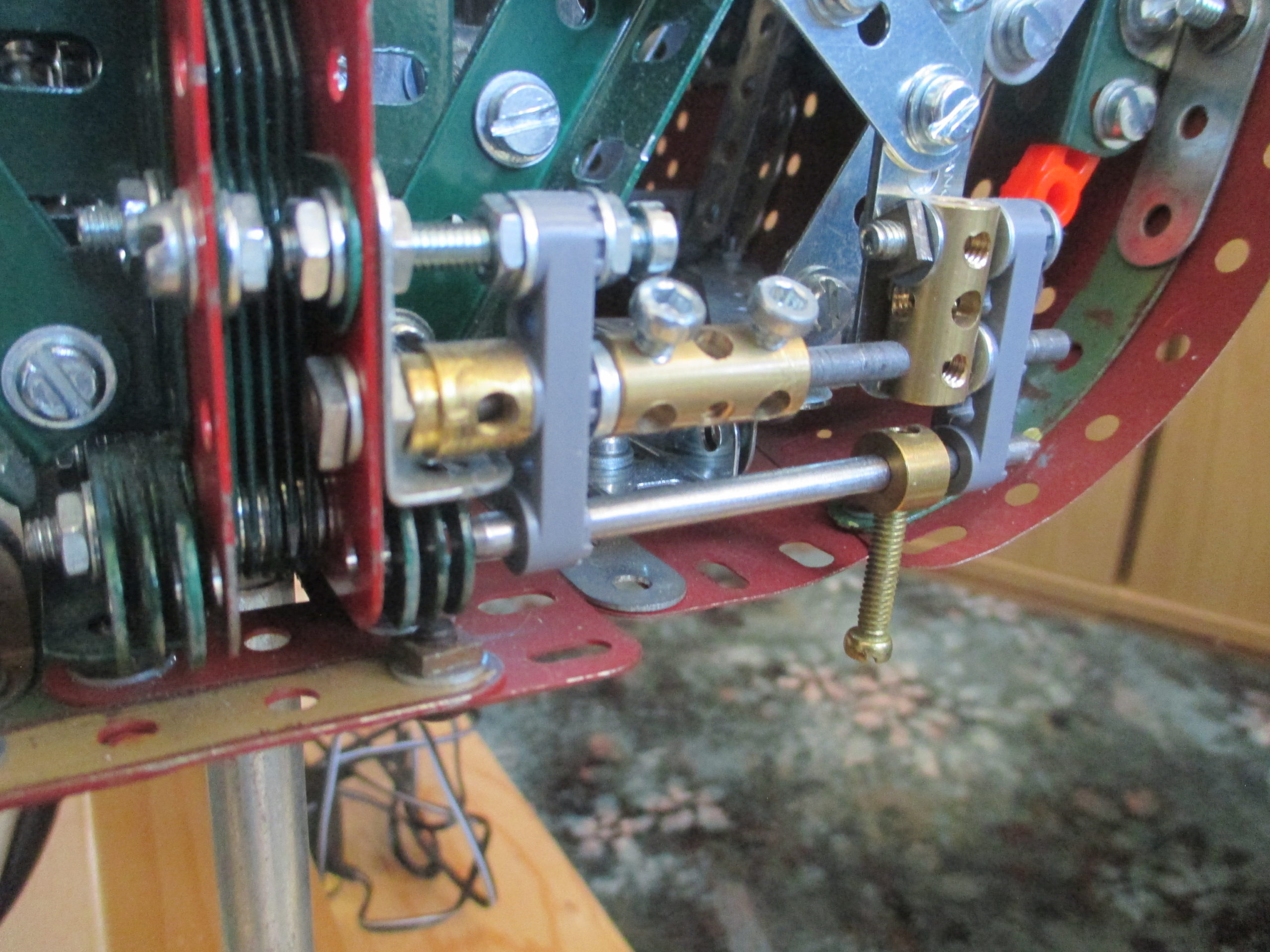
Each side has three hinge points along the hinge line. The hinge pins themselves are attached to the keel using short threaded couplings, and the pins are short lengths of Meccano rod with a tapered nose.
The short couplings are spaced off the keel’s angle girders by a washer which therefore gives the facility to adjust a pin’s height up – or down – as necessary, to ensure the hinge line is perfectly straight. The other half of each hinge is a handrail coupling mounted on the end of a tri-axle (to prevent it rotating out of alignment) which extends inboard to bridge the gap. The tri-axles are bent downward slightly to give more clearance to the keel when pivoting the side panel down. Even so, the amount it can be lowered is limited by this geometry, so the panel has to be removed for access, not just pivoted down.
To allow removal, the panel is slid aft off the pins and lifted away. Getting it back on is little trickier as visibility to line things up is limited. To aid refitting, each hinge location has a guide below the handrail coupling which supports it at the correct height to slide onto the pin.
Also, the engagement of the three hinges is staggered, such that all three do not have to be perfectly aligned before sliding to engage. Once the first one is engaged a bit, the next can be lined up without actually needing to see it. This does mean that the last pin isn’t engaged much, but it doesn’t need to be.
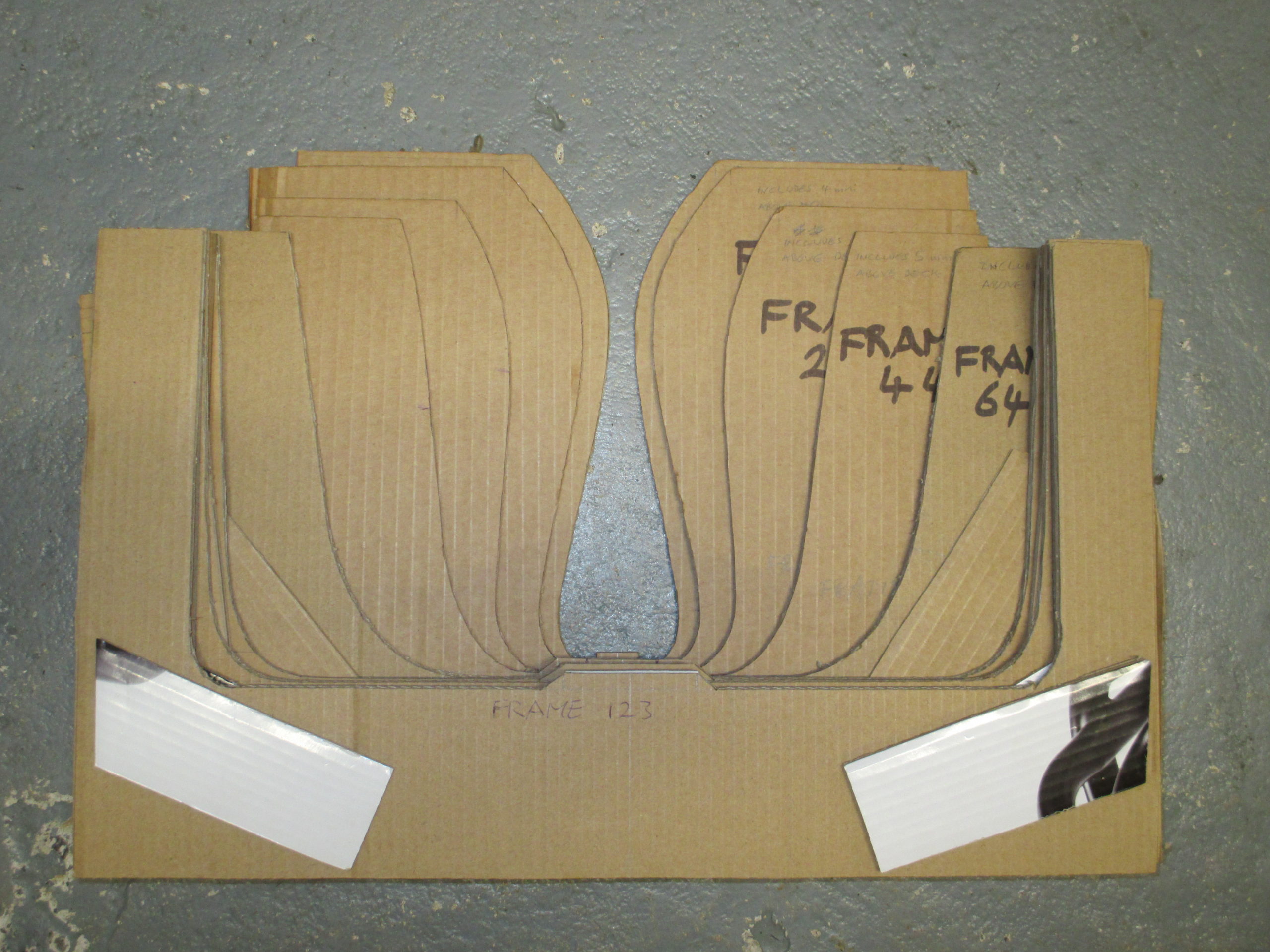
A set of cardboard cut-outs of the adjusted cross sections was made to guide the shape of the hull when plating it. The ones in the photo are for the bow section.
The raised portion at the bottom of each guide is to hold up against the underside of the actual keel, so the step represents the additional depth added as previously explained.
Each flexible plate was curved by hand, aided by tooling of varying diameters to form it over.
Mostly, each portion of the plating was done twice; firstly with scrap plates to prototype what was needed, then again with good plates (already stripped of their original paint).
Painting of the plates was done after forming into shape. Most of the hull profile in reality should be double curvature. However, for the model each plate is only curved in one plane, and each adjacent plate is progressively positioned to follow the hull curvature to produce the illusion of double curvature. This does work quite effectively over a model of this size.
Above the waterline the hull is painted in ‘Haze grey’. Below the waterline I used Halfords red primer. The two colours are separated by a black line at the waterline, which by coincidence corresponds to the lower edge of the long flexible plates used above the waterline. This made measuring and masking off easier. This was not the case for the bow and stern sections where the panelling was more difficult.
The paint finish is easily damaged, especially the red primer which marks at the slightest touch. The hull is the most vulnerable surface to be knocked, so after painting each panel – and before fitting it - it was sprayed with clear satin varnish for protection. Allen head bolts have been used for the plating above the waterline to blend in with the grey better. The exceptions are the panel attachment bolts near the top edge, which are black allen heads to denote their location.
For the black line and below the waterline, black allen heads have been used as they go better with the red panelling. The exceptions here are where longer bolts were needed, as black bolts only come in the standard length.
The top of each side panel is edged by strips, mostly 12½ inch ones which are of a decent thickness to hold their shape. This puts the top edge right up to the main deck level where there is no structural strength, so the upper attachment points for each panel are one row down, screwed into captive nuts.
The forward end of each panel curves in towards the bow, allowing the Bow section panelling to overlap it during model assembly. This gives quite a well hidden join.
The aft end is ‘squared off’ as there is very little taper, except for the underside which is already sweeping upwards towards the stern, allowing the corresponding stern plate to overlap it.
There were some awkward areas to attend to around the electrical connection port and connection pin ‘handles’.
At the forward pin a gap has been left for the pin ‘handle’. The pin has a flat filed into it to provide a positive seat for the 'handle'.
At the aft end there are two gaps allowing the pins to be slid outboard to engage.
The pins sit in guides to hold their position ready for sliding, but once engaged the rear end of each pin is less constrained to avoid it picking up load.
The aft support posts also had to be avoided for when a side panel is slid aft for removal. These areas are some of the very few locations where I had to fettle the parts with a file for clearance. In this instance it was the edge of a rigid plate to avoid a nut on the side panel for both Port and Starboard sides.
The Port side panel displays a complete hull, but the Starboard panel has been built with an opening for those interested in seeing the internals. The framework is much the same as for the Port side so is easily reworked to also be a complete panel – if it was ever needed to be.
With both side panels completed, the next task was to clad the bow and stern, both of which have far more curvature to deal with, described in part 8.
