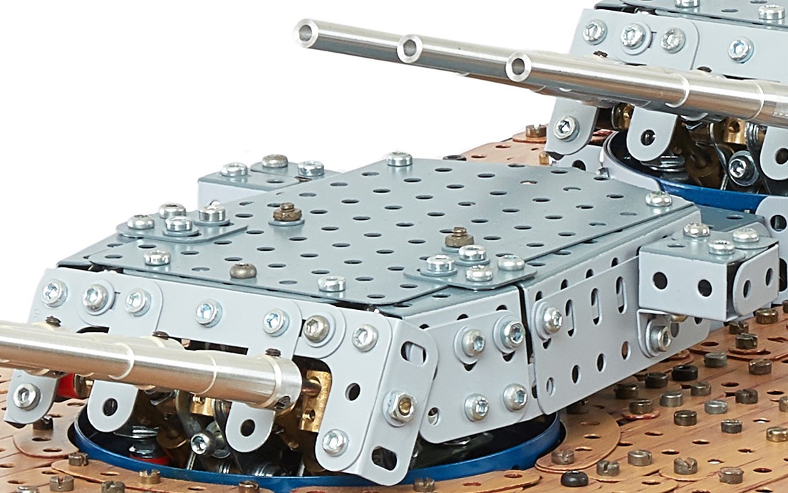
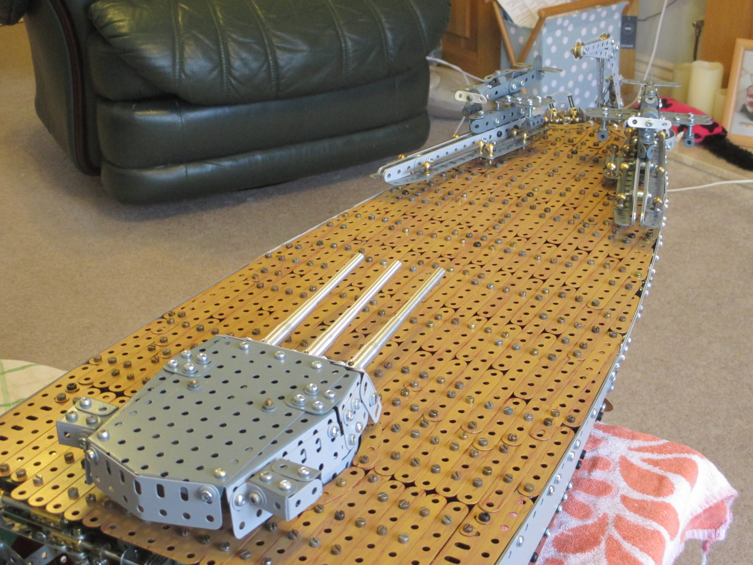
With the hull fully plated, next on the list was to finish all things topside, starting with covering the main turrets. The three turret covers are identical.
The tops are large rigid plates, with angle girders positioned to give the correct plan view shape. The angle girders were opened up a little to be more than 90 degrees before painting, because the sides of the turrets have a slight slope.
The turret cover is attached to the turret chassis by only two Meccano hex nuts. The three barrel slots at the front of the turret allow the cover to be easily lifted up and away. I did try to make some black rubber gaiters to slip over the barrels and cover the slots, but the barrel elevation and recoil actions proved too difficult to accommodate. Also, I didn't want to glue anything in place, so attachment would have been problematic.
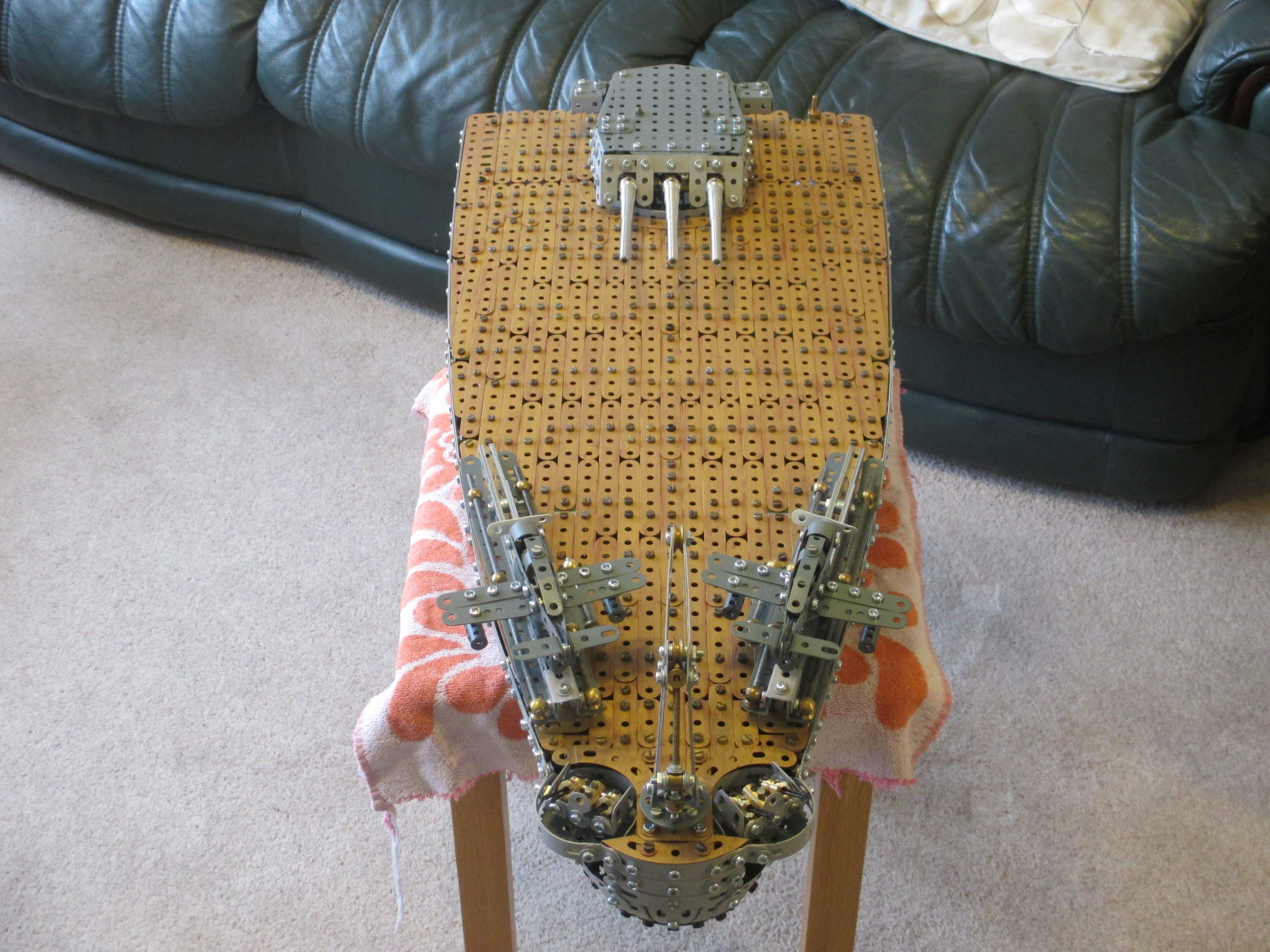
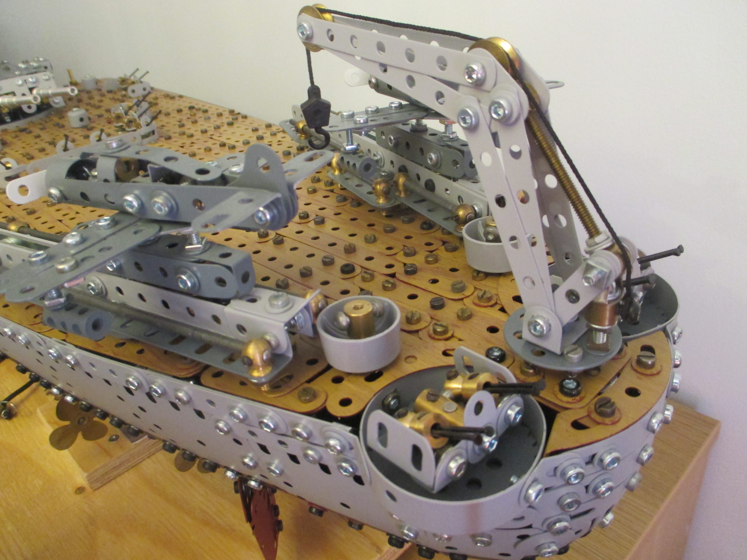
The stern deck is quite a large expanse, and comprises several deck panel assemblies. At the very aft of the deck are a crane and two observation floatplanes mounted on their steam rails ready for action. Also here the decking has to accommodate the two sunken Bofors gun emplacements, plus allow attachment for the crane.
More brassware provides for captive nuts for the small decking subassembly around the guns.
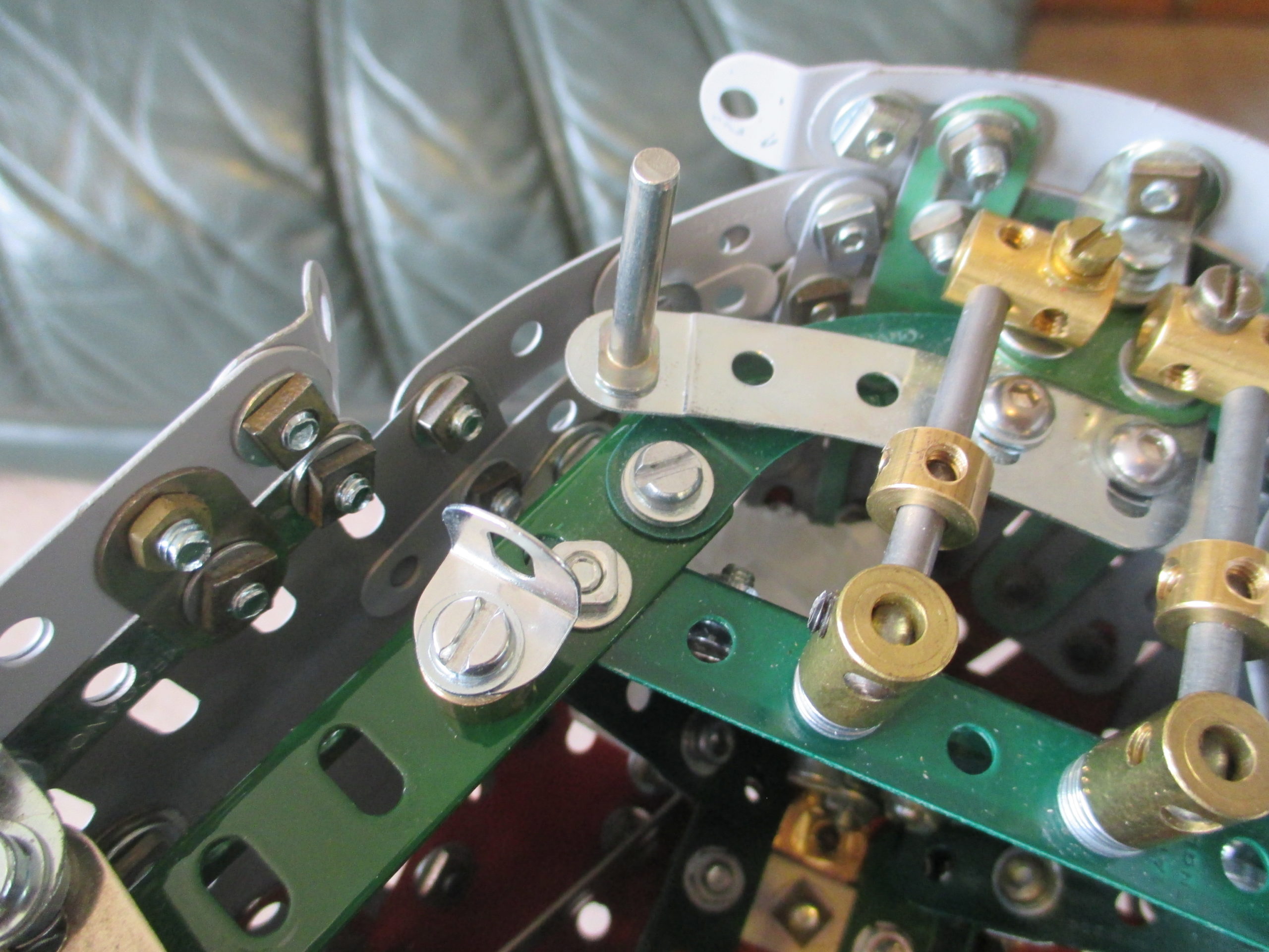
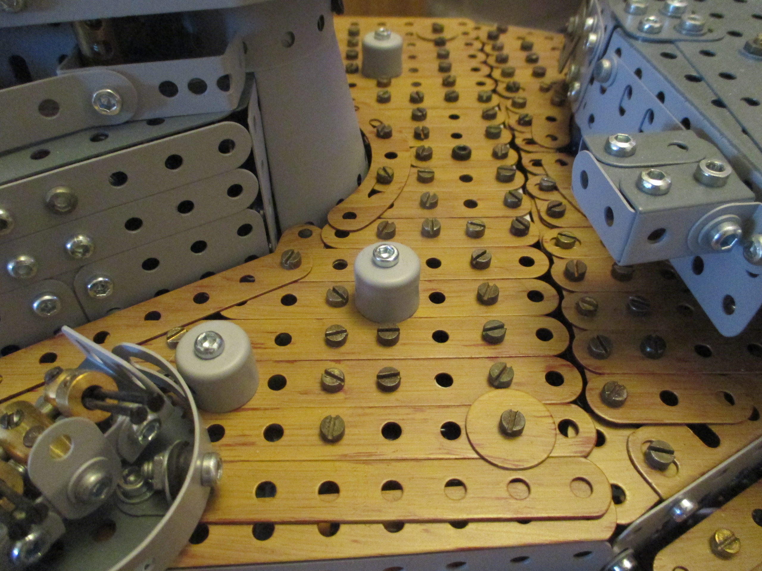
There is a small amount of fixed decking around the supports for the steam launchers to simplify the removable decking a bit (note the zinc bolt sticking up near the top of the picture).
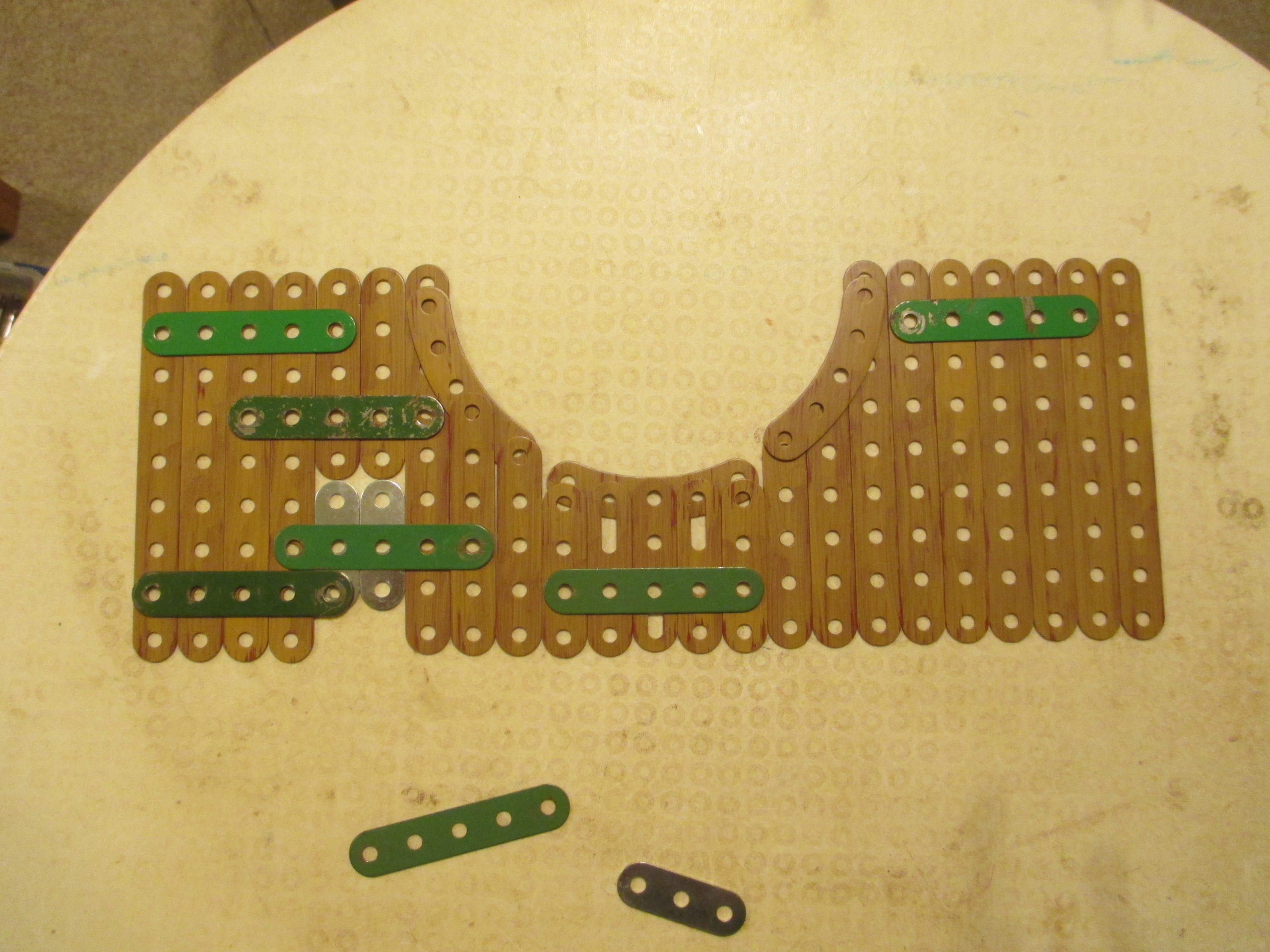
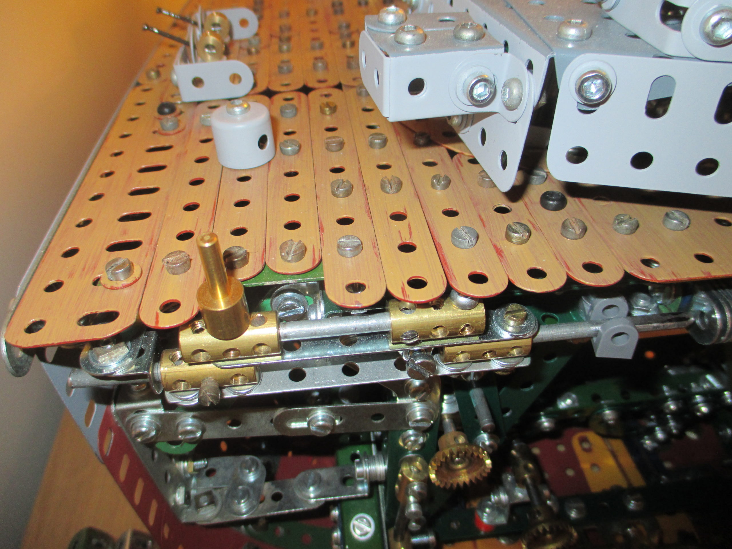
The remainder of the decking is done in two large panels, split across the middle of the main turret barbette. Like before, the underside of each panel is supported by staggered strips.
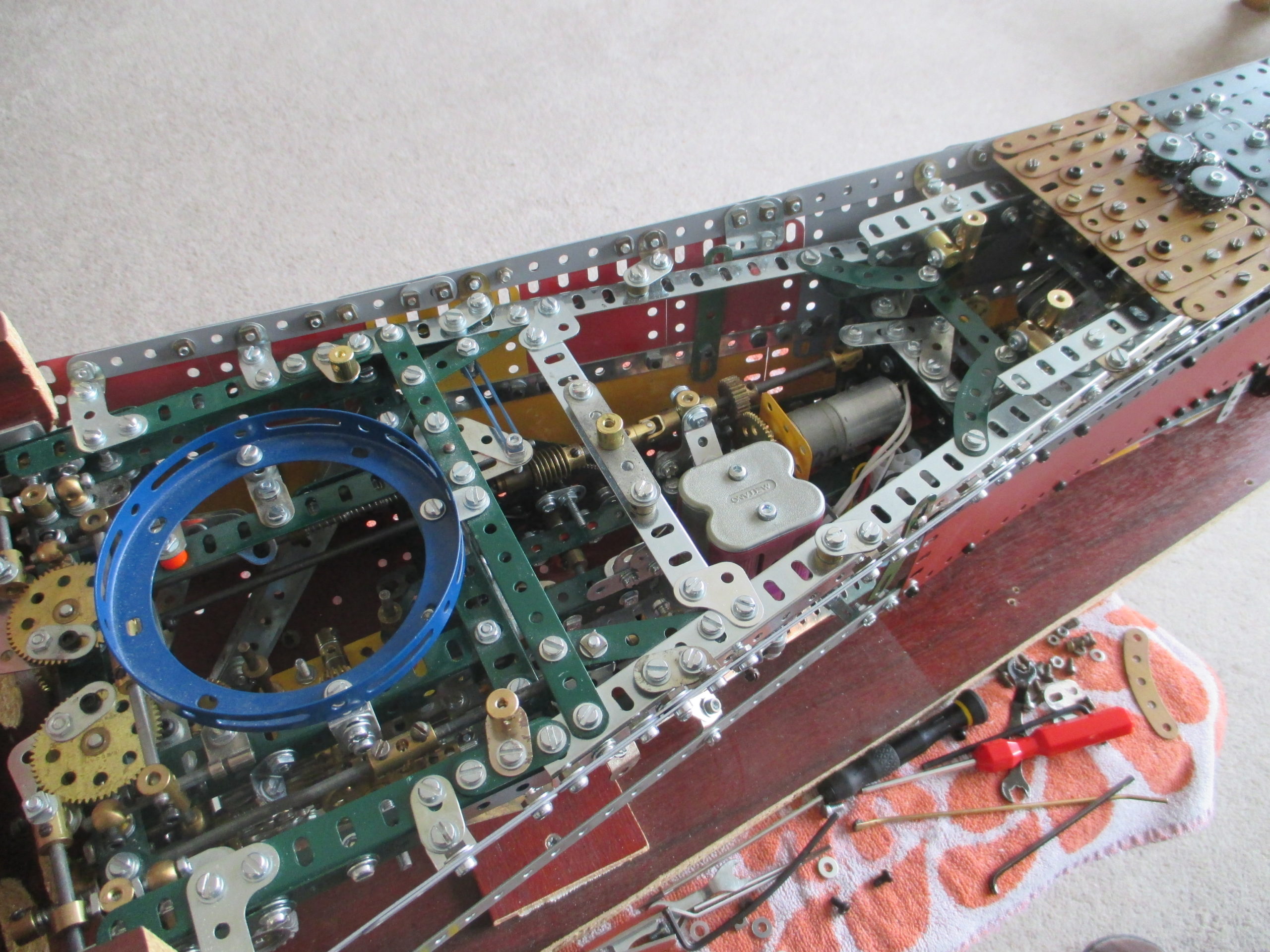
The underside of the largest panel includes two threaded cranks down the middle, which allow long bolts (as seen in the earlier picture) to be screwed into them from above. When inserted, these two bolts become handles for lifting the panel for installation and removal. Multiple black allen head bolts secure the panels into place, screwing into captive nuts (threaded bosses).
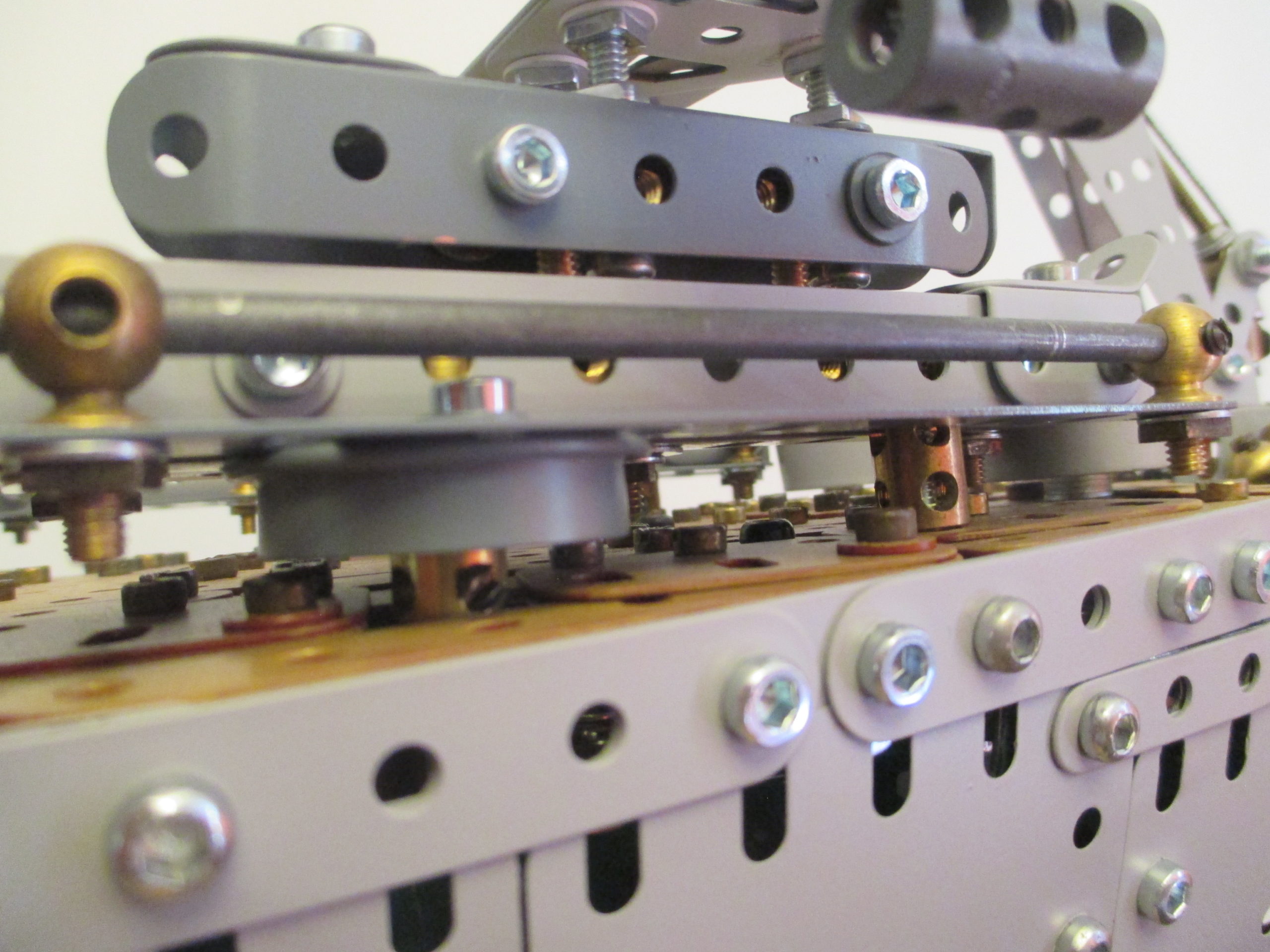
The main deck panels are not flat, but have a camber as per the real ship. This feature is to encourage water to run off to each side of the deck.
The Vought OS2U Kingfishers had a central main float plus two outriggers, and were launched by the two steam catapults which swung outwards.
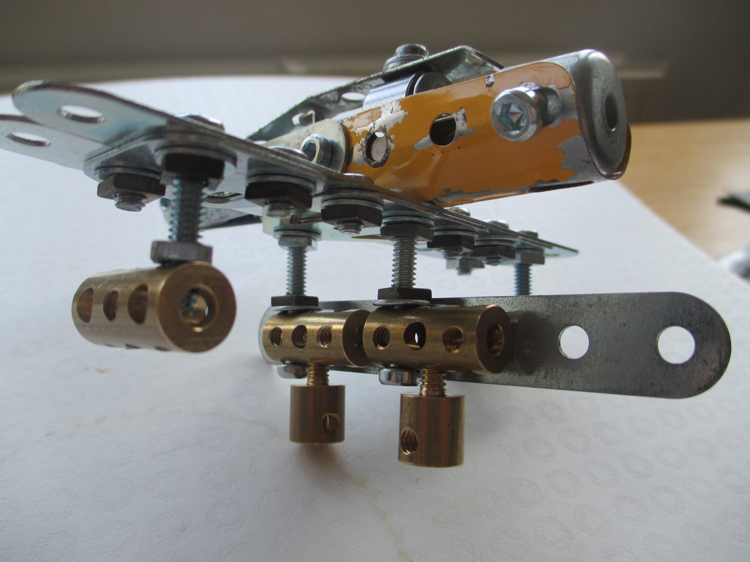
After some tight bending of a few things and some paint, the model planes are a fair scale representation of the real thing. They are firmly secured into the steam rails via two rod sockets.
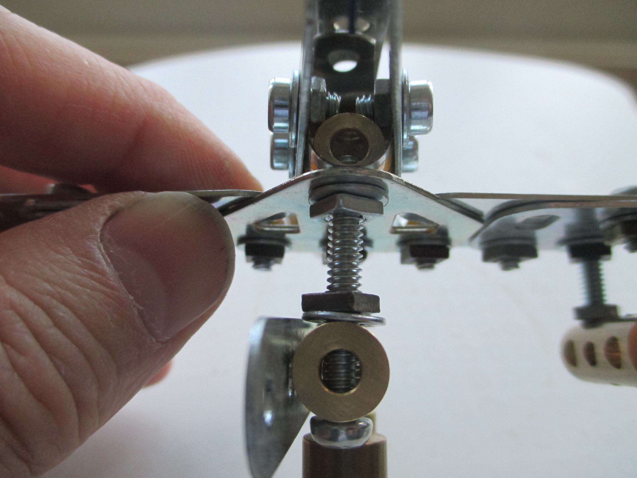
Each steam rail is supported on an upturned flanged wheel, with the wheel tightened onto a rod protruding from the deck. Towards the rear of the rail, a coupling locates between the rail angles to secure it from pivoting about the rod.
Just behind the steam rails are two gun director stations (for the adjacent Bofors guns) which are simply painted Modern Meccano wheel centres.
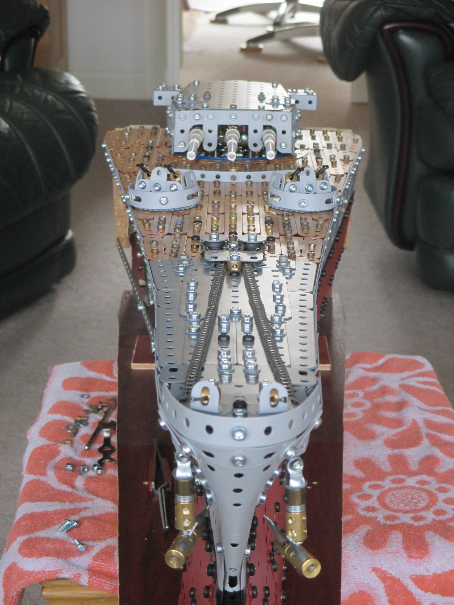
The bow deck did not have teak all the way to the prow, so the model only has the wood effect up to the anchor capstans. Flat girders have been used at the sides of the front decking as there is no room for bolt tails and nuts because of the flare of the hull.
The largest portion of deck back to the turret barbette includes the two Bofors gun emplacements and the water diverter.
Again, threaded cranks have been used to provide a location for lifting handles. The panel actually has double curvature because of the curve up towards the prow as well as the camber. It is bolted down into many threaded bosses used as captive nuts as seen in the picture.
The anchor chain capstans are just for show. There is a little bit of chain wrapped around them to give the illusion of the real thing. The chains actually divert down just forward of the capstans.
The remainder of the main deck is on the centre section. The two principal difficulties were getting the deck joins with the other sections to be as discreet as possible, and leaving a close fitting aperture for the superstructure to drop into.
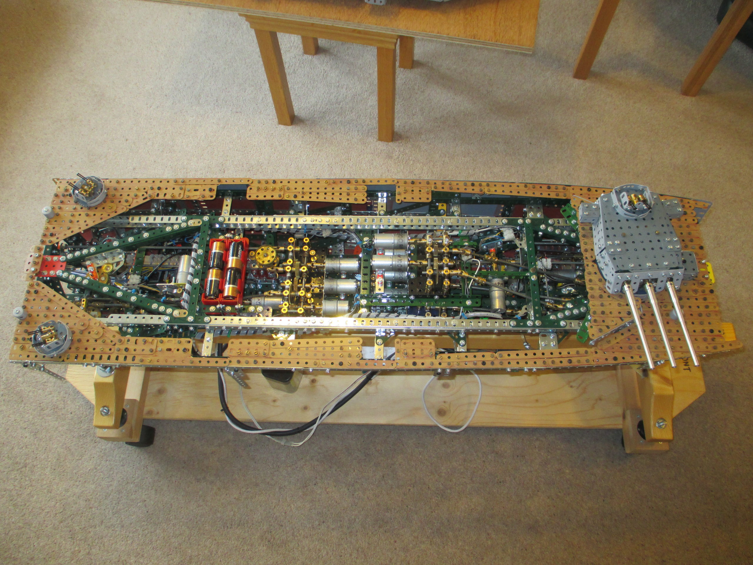
With all the individual subassemblies bolted down, the aperture for the superstructure can be seen, including spaces for the lower 5 inch gun turrets.
Note that to lift the superstructure off, the number 2 turret has to be positioned at 90 degrees to give clearance. This is why having battery power available is useful.
At the deck join line between the centre section and stern section, a small gap has been left on the ‘non public’ side. This is to allow the handle of the connection pin to slide inboard. The forward deck join has no such need as the connection pins are inserted remotely by turning the thumbwheel.
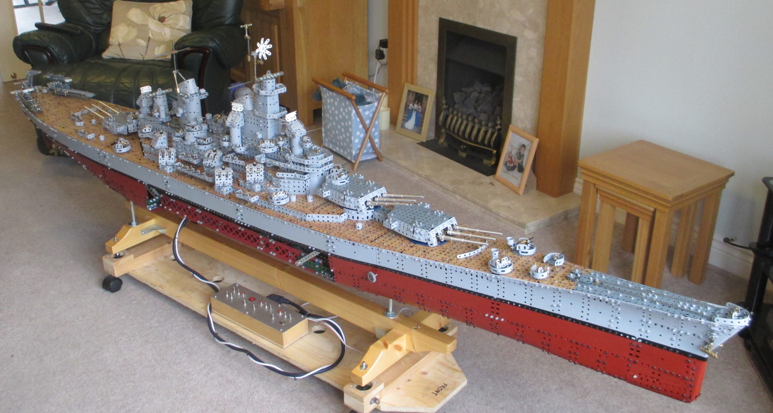
The last details to go on were the remaining Bofors guns and machine guns, and quite a few ventilation pillars. The assembled finished 9ft model looks huge in the lounge (viewed from the non-public side), and there is currently nowhere in the house that has a clear 9ft space to keep it assembled.
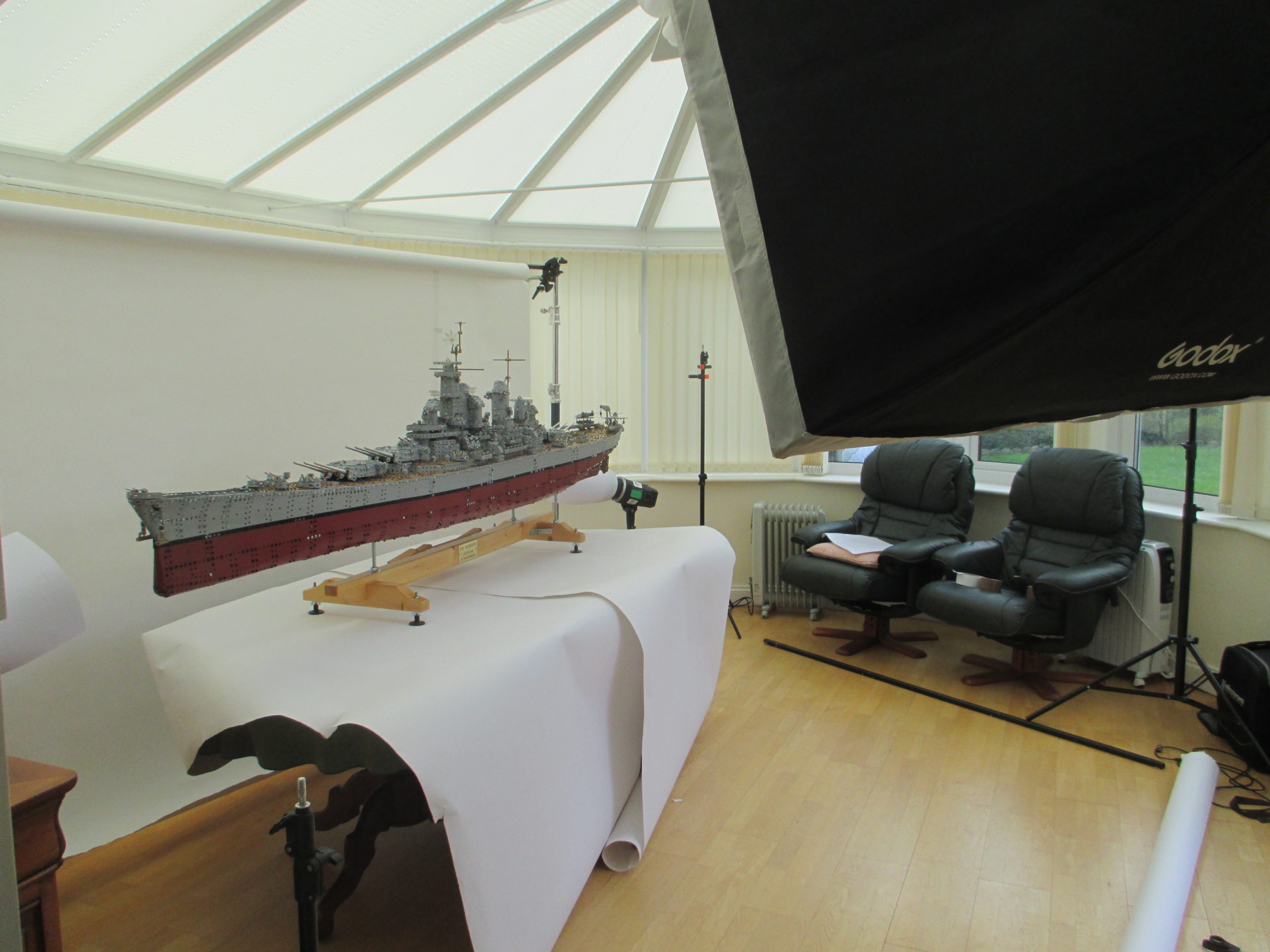
It does fit in the conservatory, but it can get too hot in summer and too cold in winter (seen here being professionally photographed for CQ magazine). It reached 55 deg C during our holiday, and would go below zero if we didn't have heaters on a frost setting. The high temperature would affect the plating.
From start to finish it took about 6½ years, which includes the planning time. Since its completion in June 2019 it has been to several Meccano and non-Meccano exhibitions, and was booked to go to others in 2020 until Covid-19 struck!
It has won the 2019 Skegex 'Issigonis Shield', and more recently the 2019 ISM 'Founders Prize', for which I feel very honoured.
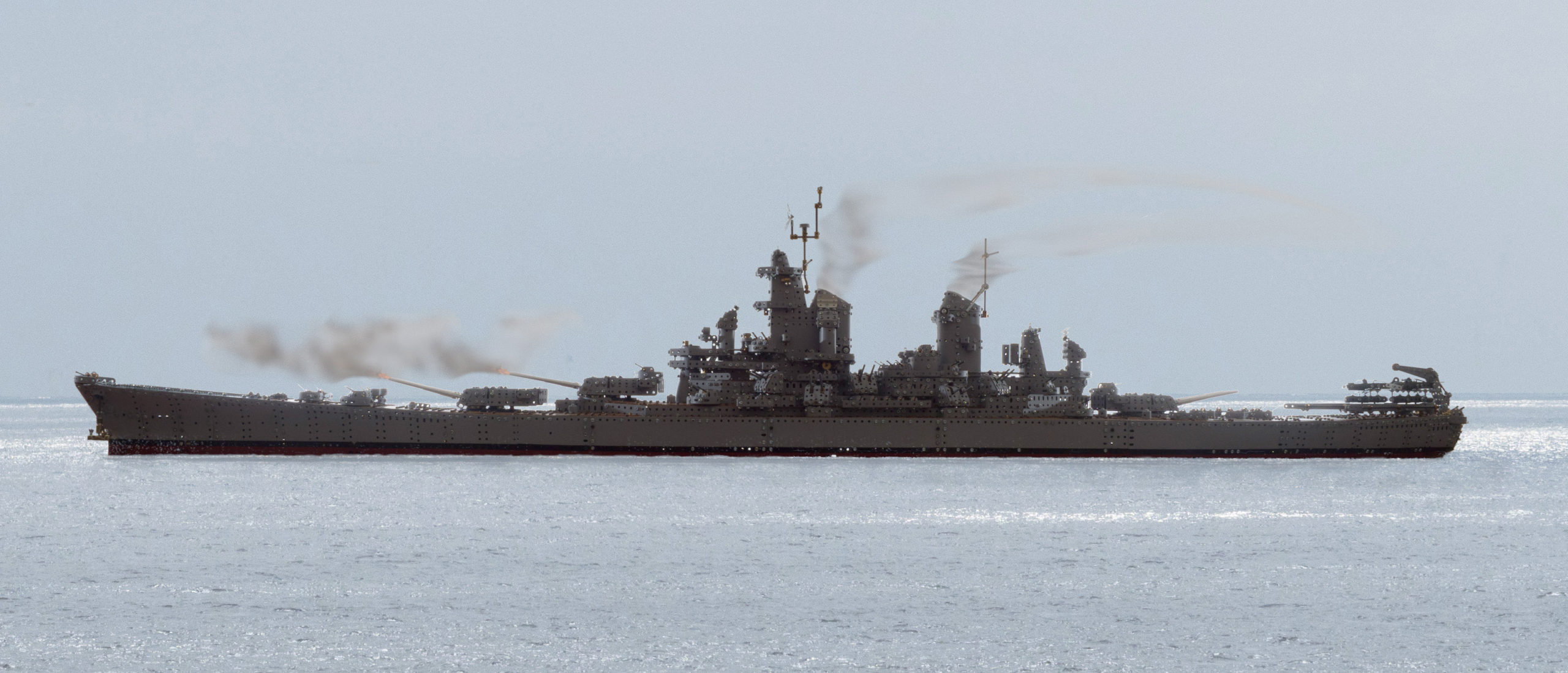
There are two videos below that show the completed ship. The first was taken by my brother Rob at St Albans MES in September 2019, with ship appearing a few moments in. The other is by Dubious Engineering taken at The London Model Engineering Show at Alexander Palace in January 2020.
If you’ve managed to get to the end of this blog, you will have read over 13,000 words and viewed 327 pictures! As a matter of interest to me, I have just counted how many 3 hole brass couplings I have left, so I now know I used 198 of them in the ship. Overall, the model consumed brassware and gears like Mr. Creosote.
Lastly, I am often asked jokingly; will it float? Well, the answer I believe is yes, it could. At 100th scale it is 1,000,000th the volume. The real ship weighed 58,000 long tons, so 1,000,000th of this is about 59kg. Without the plinth the model weighs 67kg, which would result in under 2cm extra displacement, still well below the deck level. As the hull closely replicates the real hull, the centre of buoyancy through the ship’s metacentre should still be outboard of the CG for small angles of roll, giving it a righting moment. After trimming the mass and covering the whole hull in plastic sheeting (plus sealing the prop shafts etc.) there is no reason why it shouldn’t float. After a few years if I feel brave enough, I might try it!
I am indebted to my wife, who is also the webmistress for SWMC, for uploading all this to the website, and of course for being very understanding during build! I don’t think I’ll be building something like the USS Missouri again.
