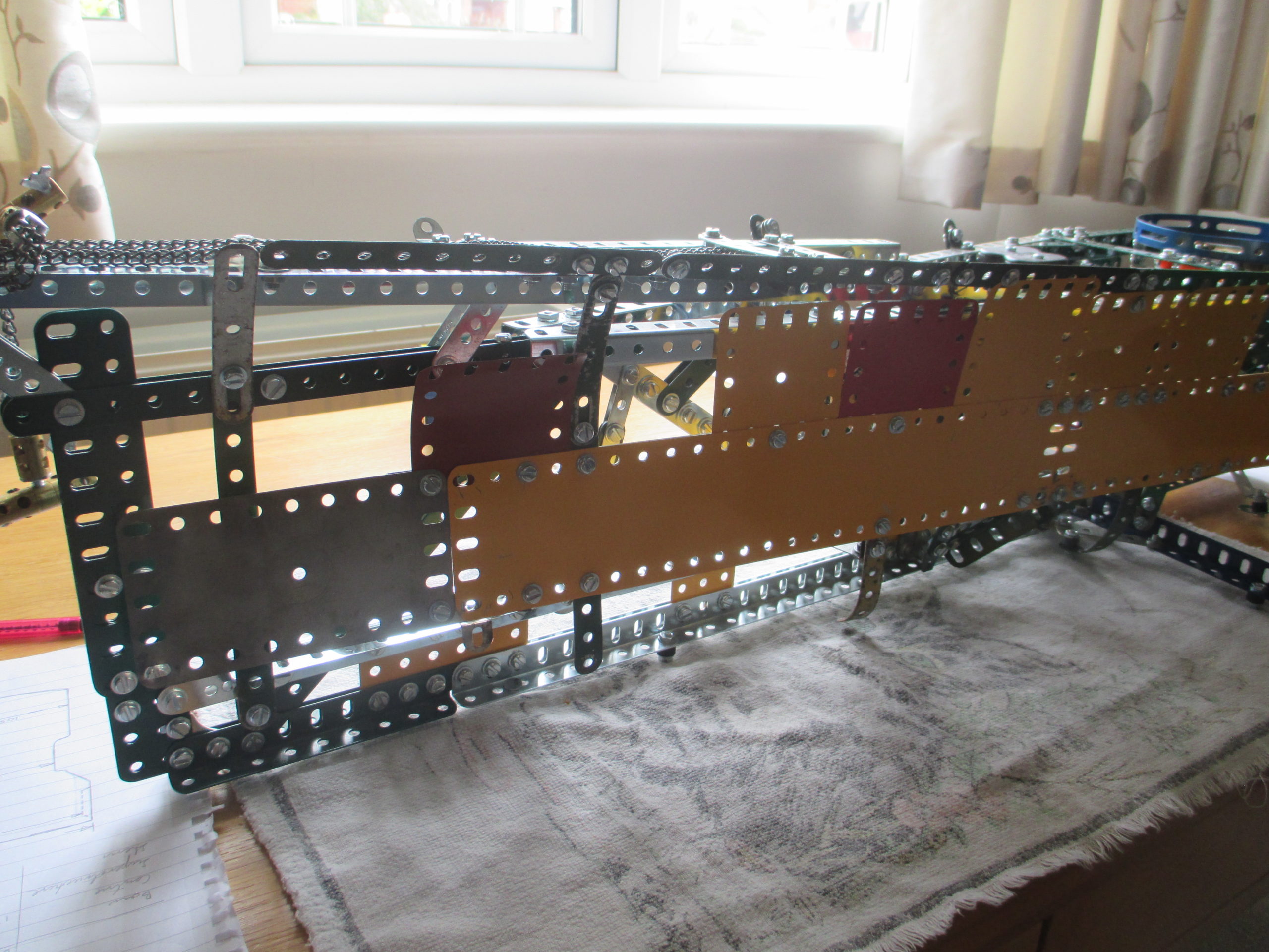
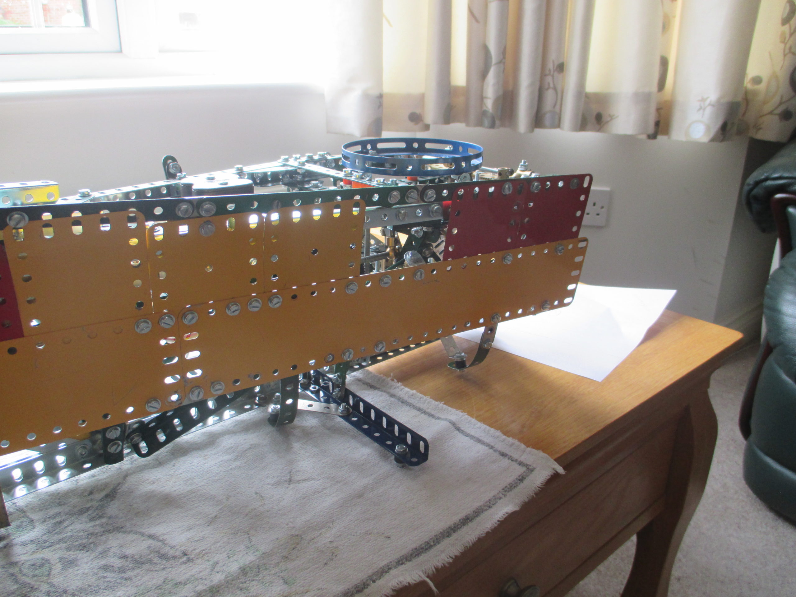
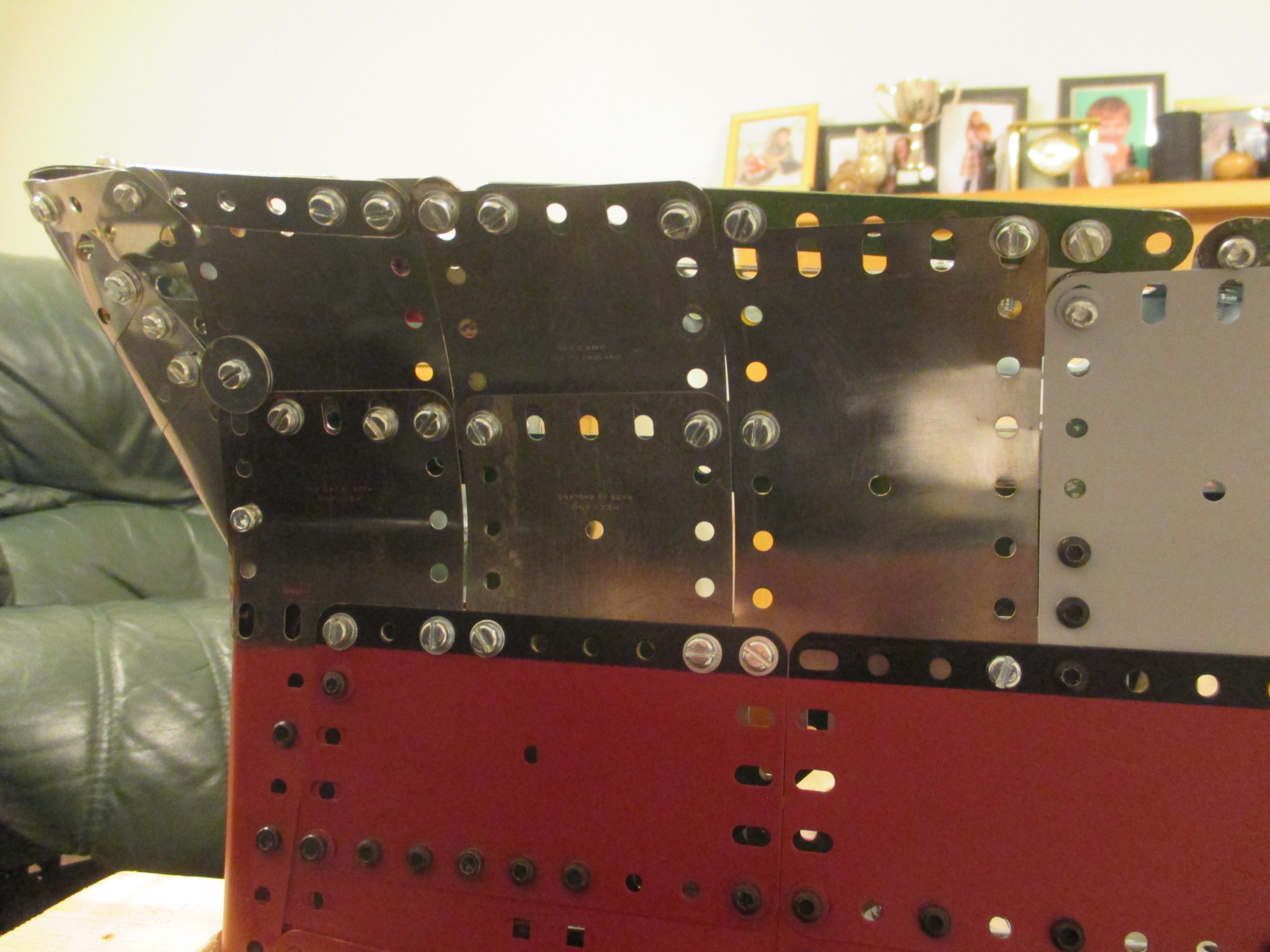
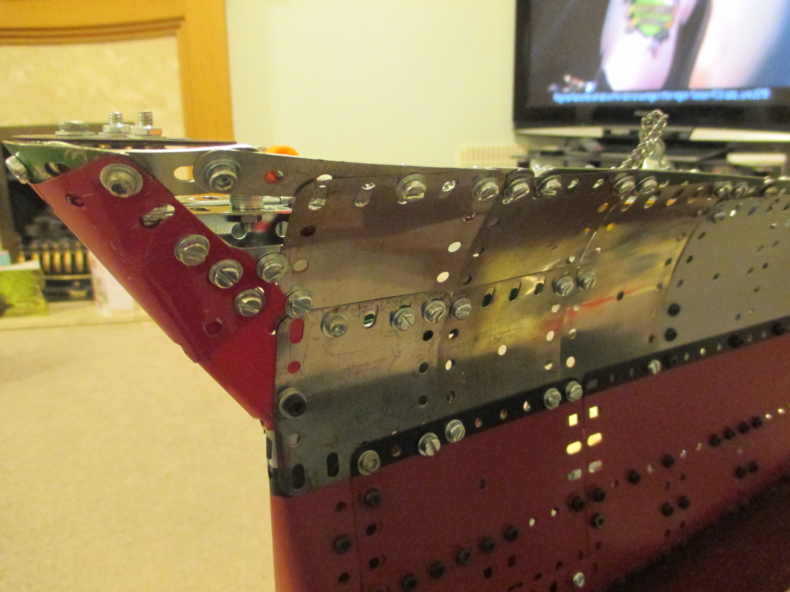
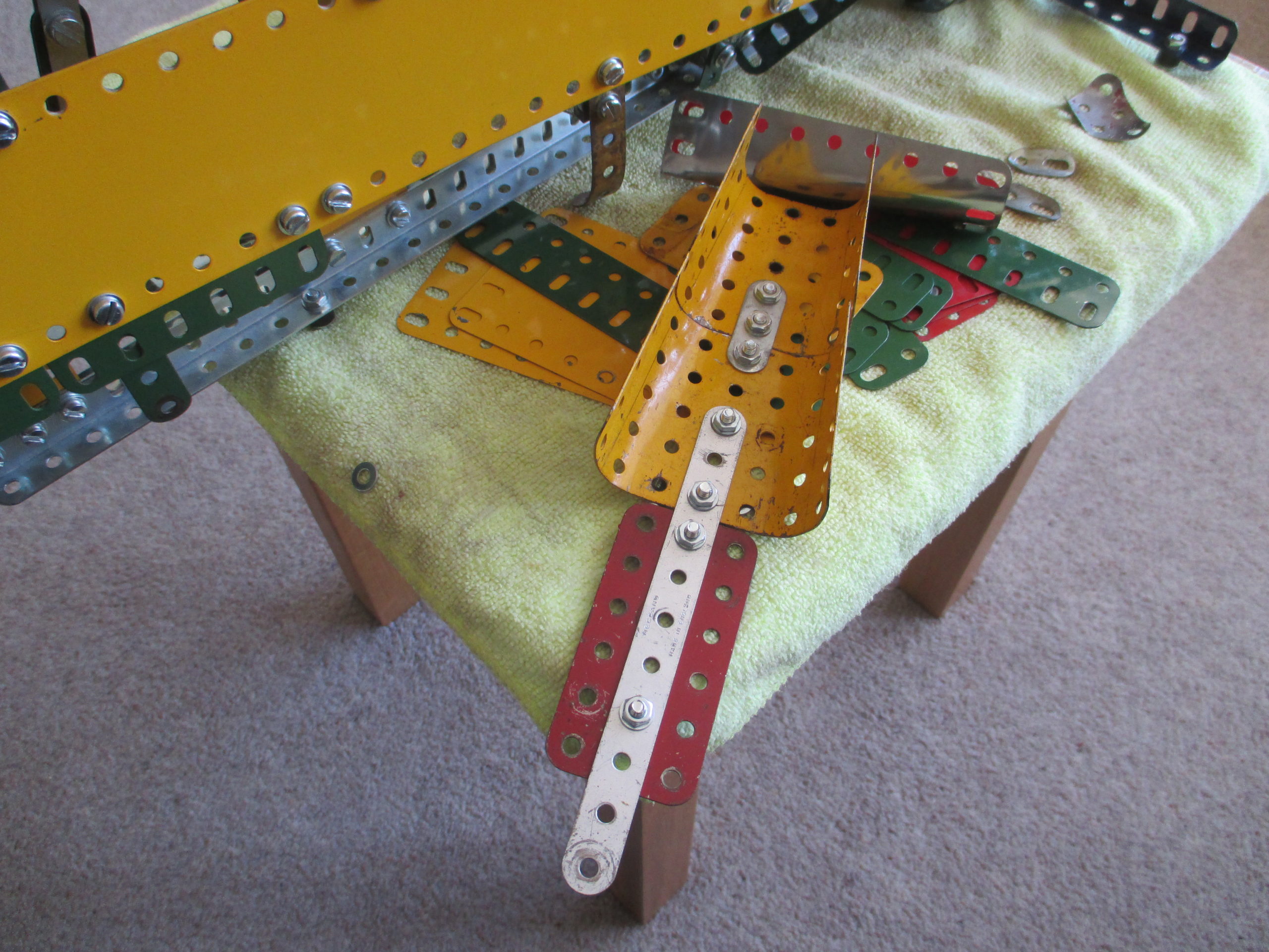
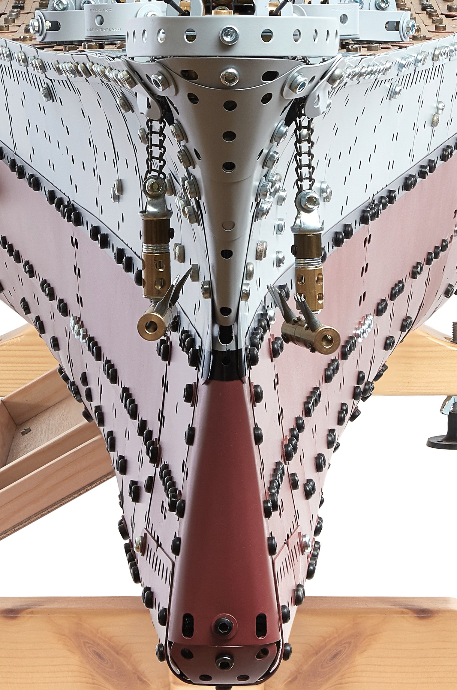
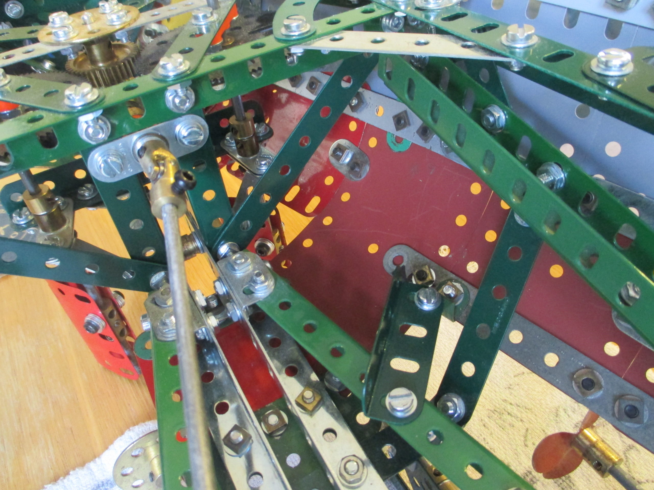
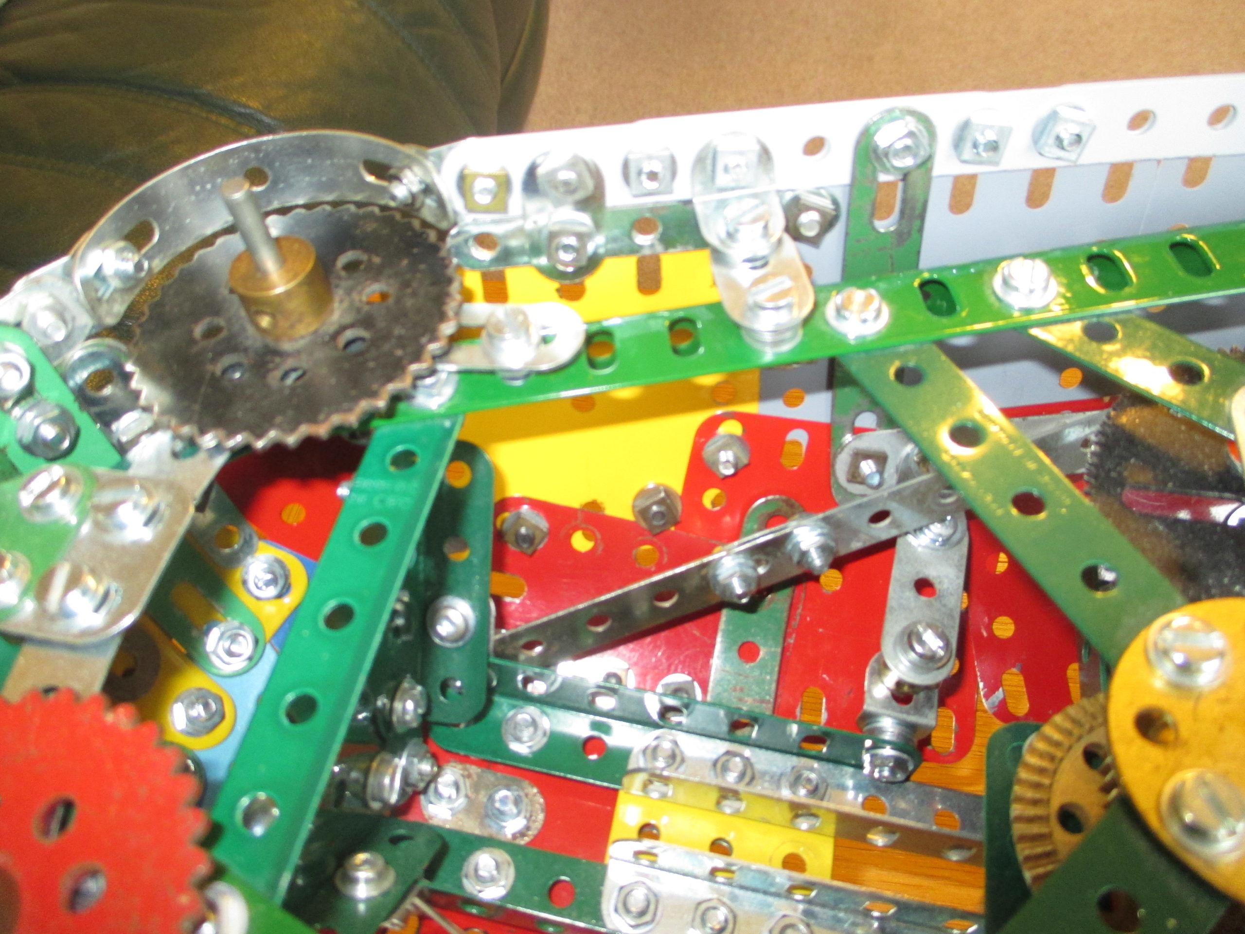
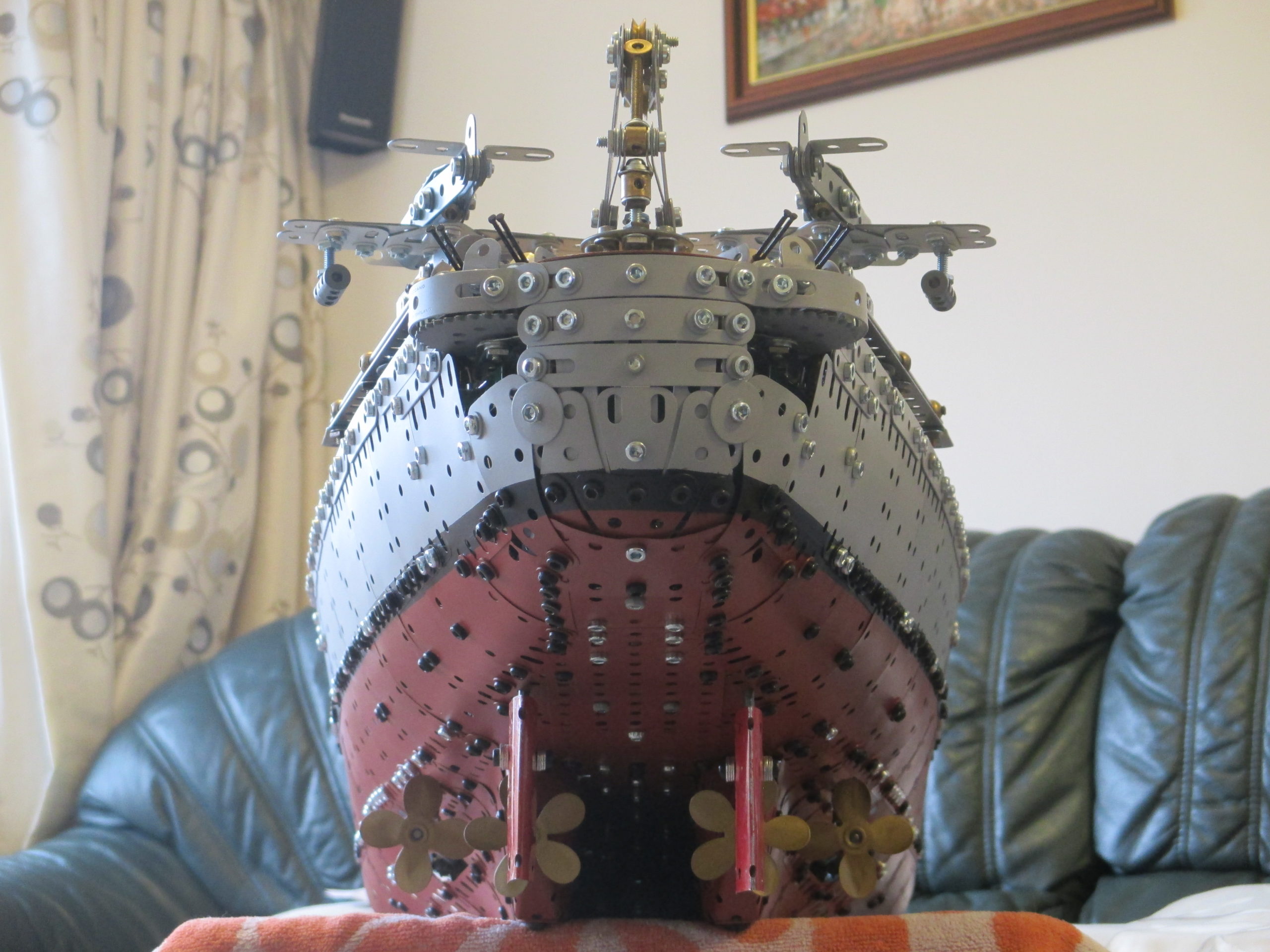
Cladding the bow was challenging not only because of the extreme curvature in places, but also the lack of internal access as it became very narrow towards the prow. Initially, a crude lattice framework was assembled around the structure just to provide a shape to work to.
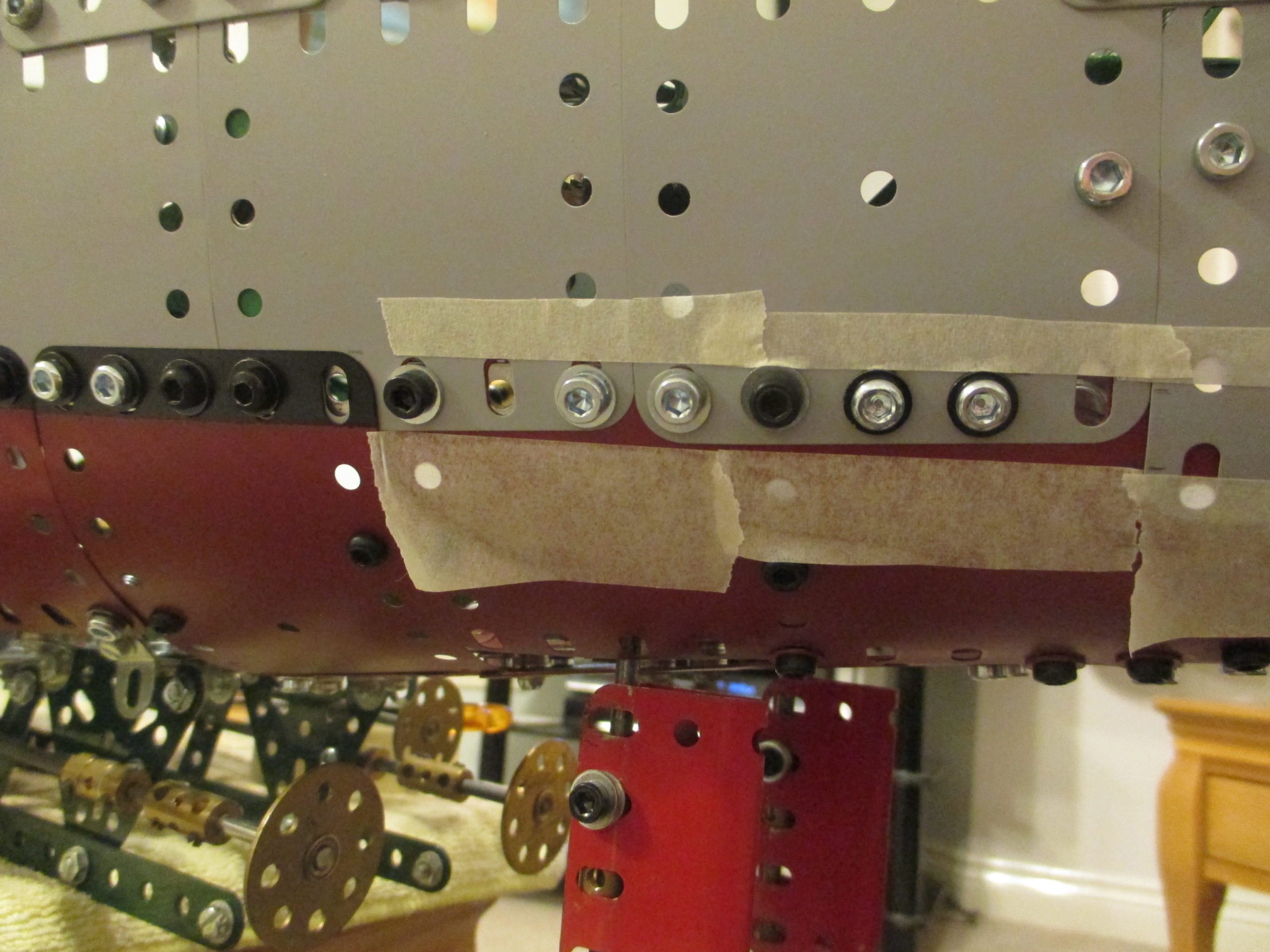
The final supports for the panels would depend on which size and shape plates were used. The one constant that needed to remain was the line of strips at waterline level to maintain the black line at the edge of the plates.
The horizontal strips were not only curved for the hull contours but also had to be twisted along their length as the hull section transitioned from tapering downward to tapering upward.
First on were the long 2½ inch wide plates which also had to twist along their length. Fortunately some of mine had a natural twist – normally an undesirable trait – so these were used with hardly any coaxing to conform.
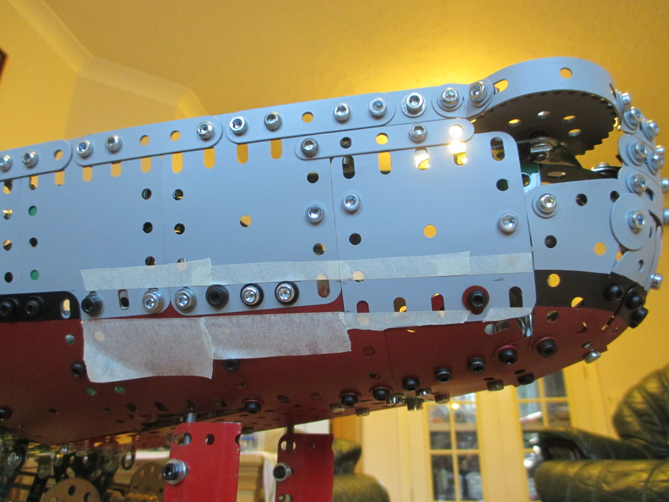
The deck rises up toward the prow with a pronounced outward flare. This was easier to replicate with small plates but meant that more fixings were needed.
The smaller plates were set with their slotted holes vertical and each adjacent plate raised relative to its predecessor. The uneven run-out at the top was dealt with later.
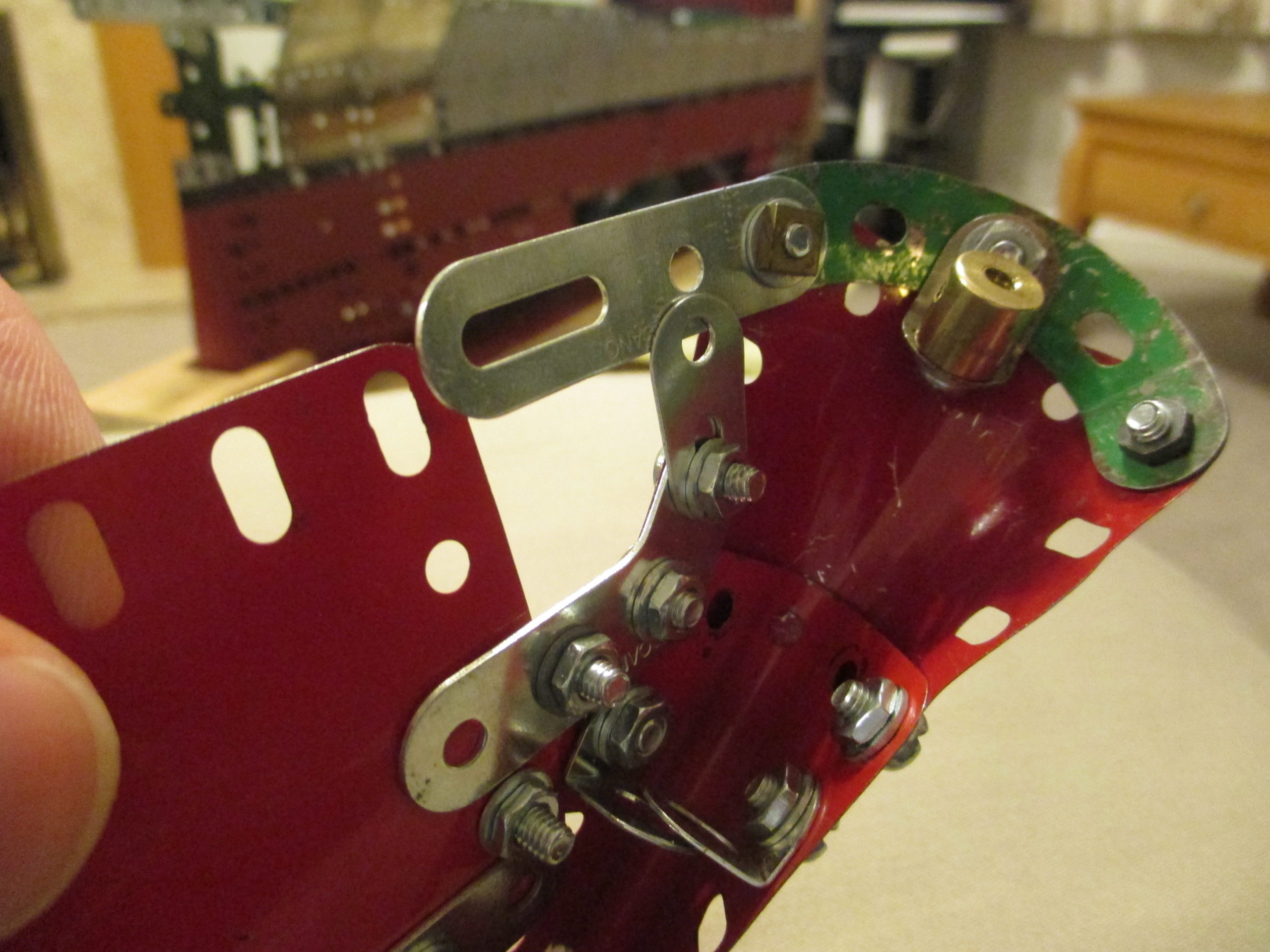
At the front things became very tight. With only one side plated the nuts were just about accessible, but with both side plated they weren’t. So where possible, captive nuts were used (yet more brass couplings).
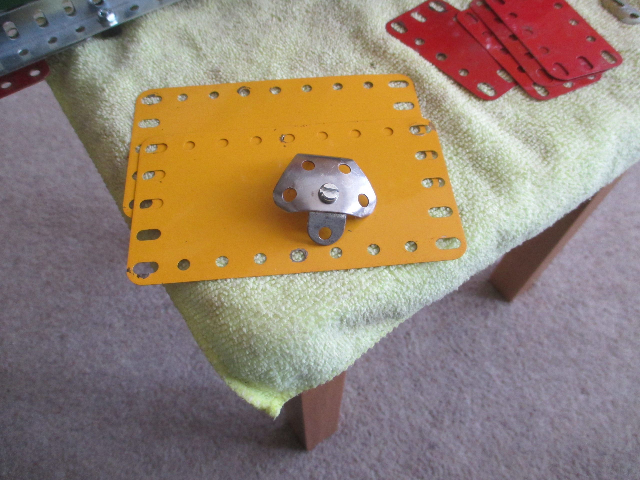
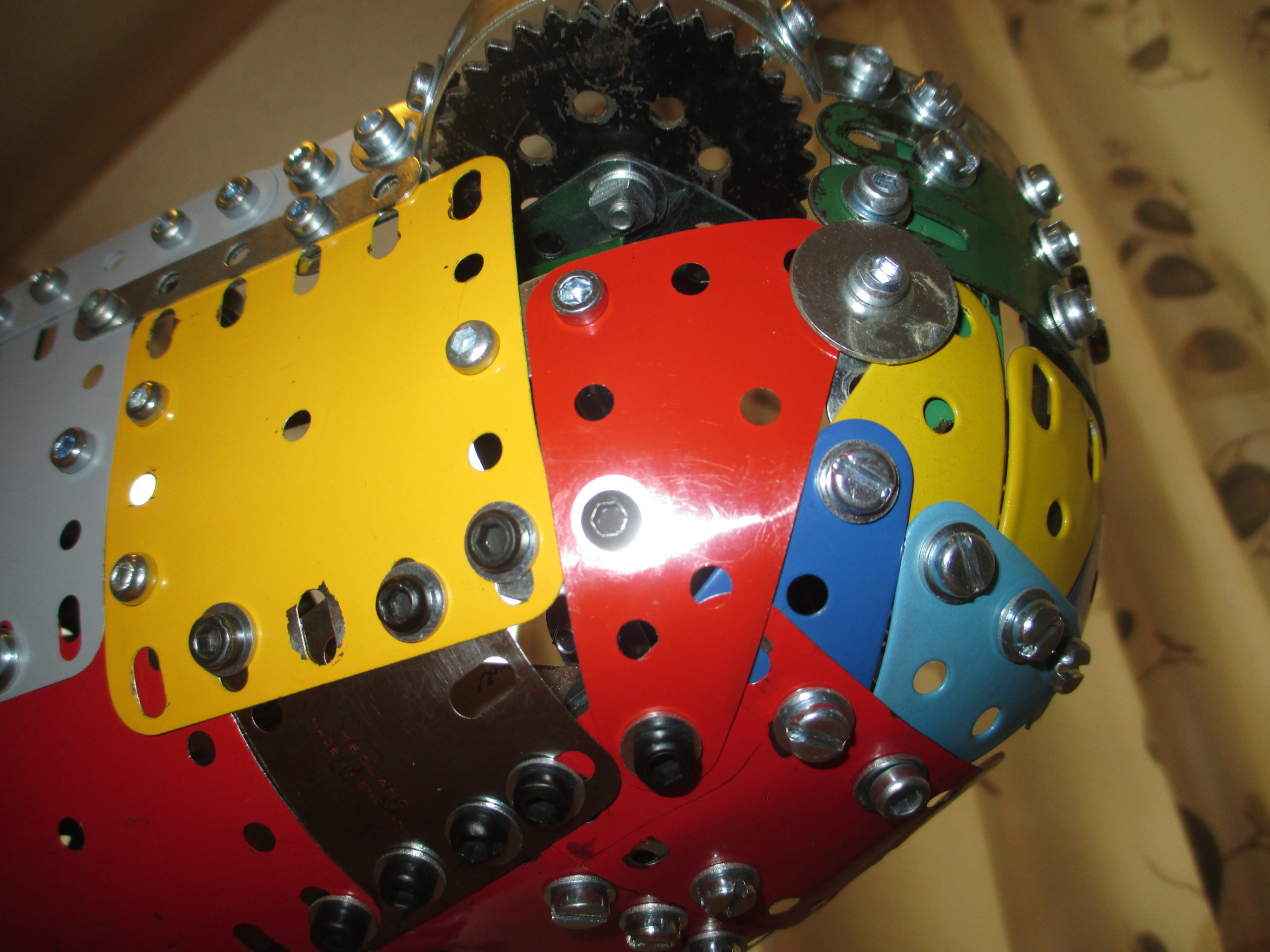
The tip of the ‘nose’ is fashioned from a modern Meccano dished triangular plate, which still had to be hammered even more to be somewhere close to the right shape.
The prow was made as a sub-assembly and installed as a module after painting, with a gap left for the anchor chains to pass through.
The platform at the prow is made from a flattened 2 inch wheel as it suited the radius needed. A pair of pivot bolts suitably angled provide a guide for the chains to run over and down through the sides of the prow.
In some places there was no possibility of holes/slots lining up for a bolt so a large washer has been used as a clamp.
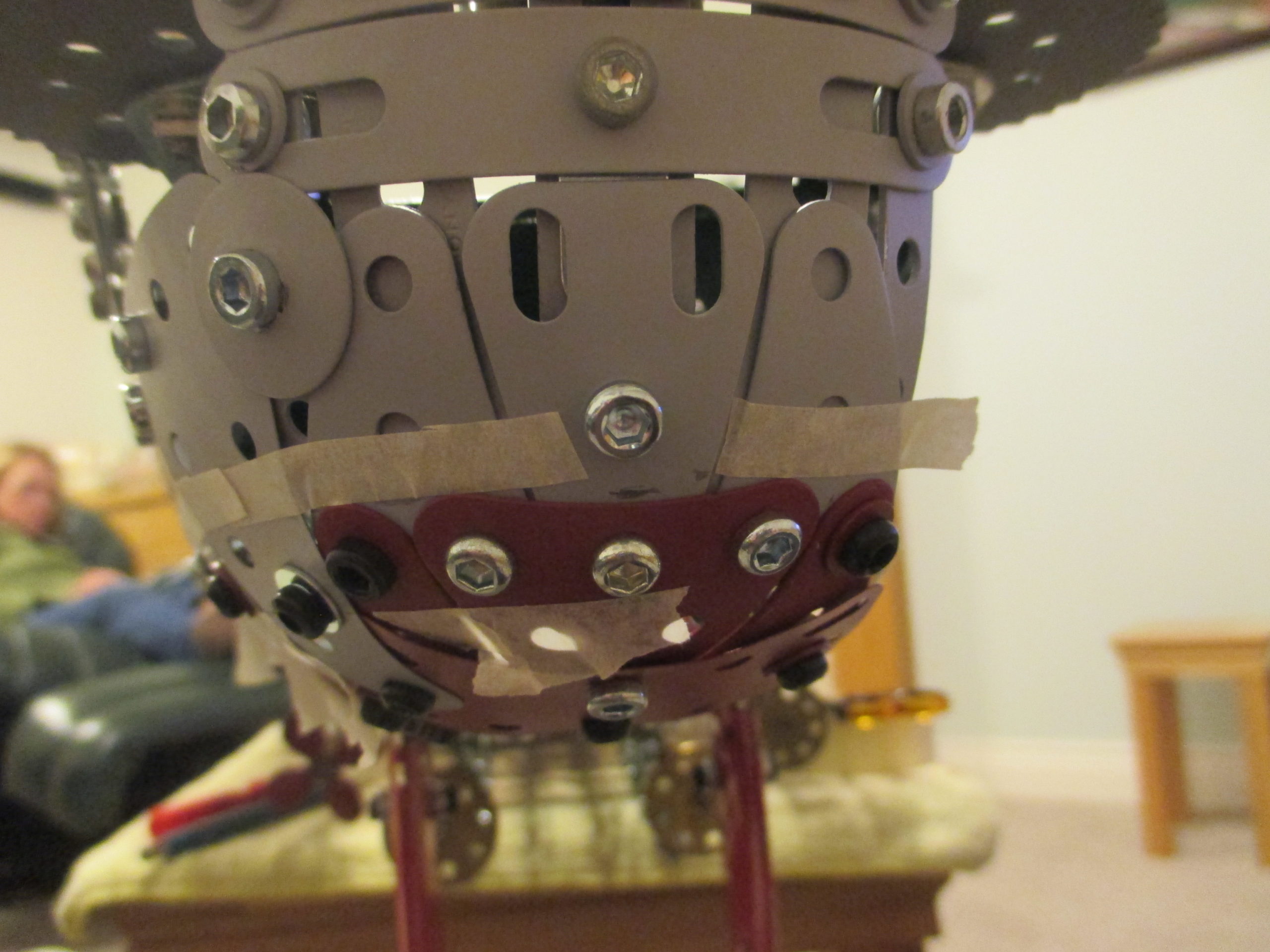
The bow needed a forward handhold for carrying, so the underside at the front is made with formed rigid plates. This provides a strong and comfortable location to lift from.
For joining the plates inside the tight curves lots of brass couplings are used. The plating was installed 3 or 4 plates at a time, working aftwards. This does mean that the forward plates are basically not removable without removing many others first.
The footprint of the hull’s underside widens as it progresses aft, and the lower edges of the plating rarely coincided with a structure hole for bolting, so a different method of attachment has been used. The rigid keel plates have another plate sitting on them from above, loosely attached with couplings as nuts.
The thin gap between the rigid plates accepts the edges of the hull plates which get clamped into position when the bolts are tightened. This arrangement is very effective and accommodates the lower edge ‘run-out’ of the plating. The clamping bolts are extra long to pass through the couplings. A self locking nut has then been used on the tail of each bolt to prevent the bolt from accidentally being screwed completely out, because they would be impossible to reinstall if the coupling came loose.
A similar clamping arrangement has been used on the plating on the rising prow, this time using short strips to give the illusion of a smooth curving profile.
Where possible the hull plates are edge to edge without an overlap to give a smooth surface. Where they do overlap the plates are as tightly pulled together as possible to avoid gaps which would spoil the effect.
The Stern
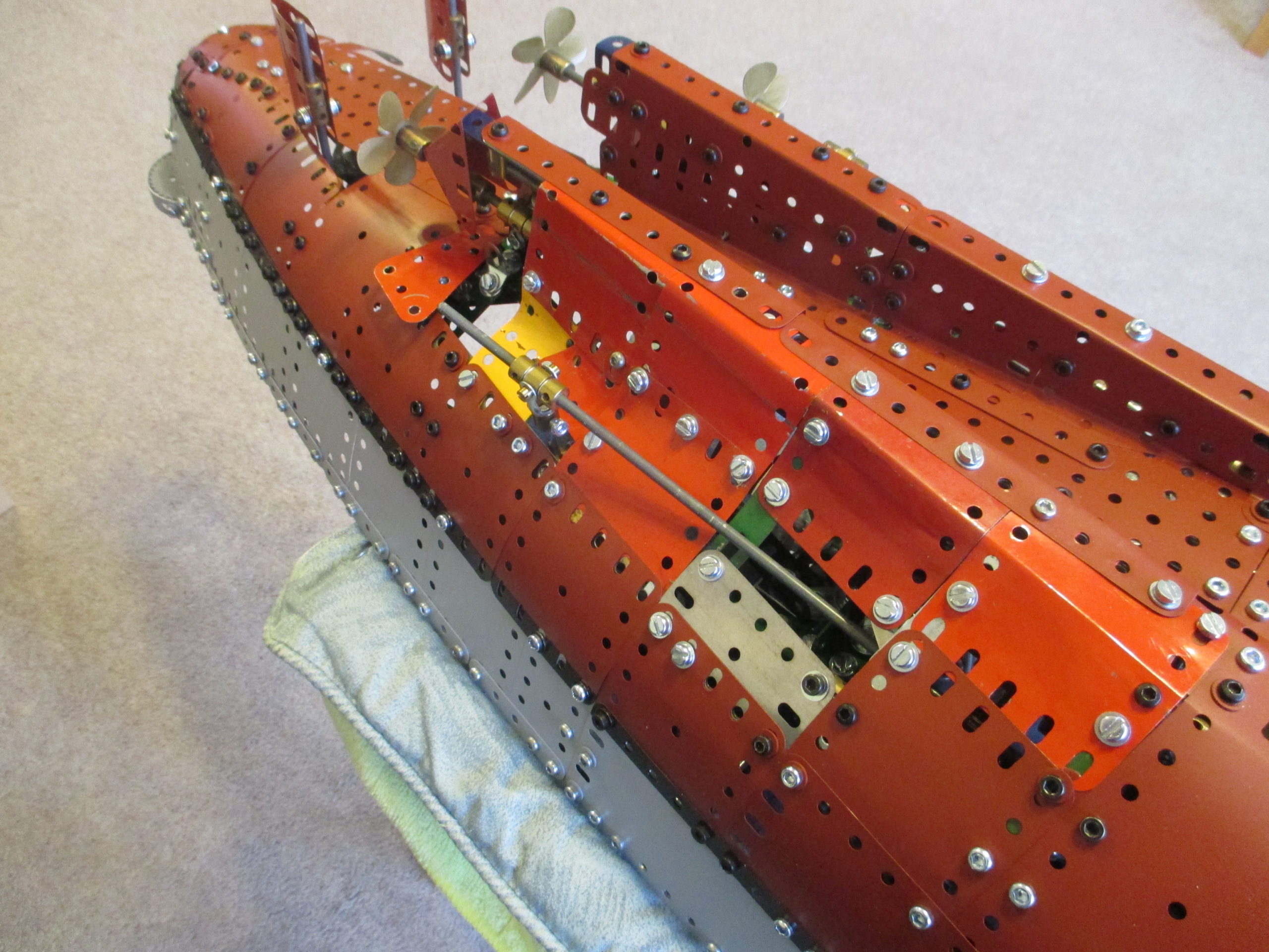
Plating the stern section proved to be the most challenging, with its huge expanse of double curvature and propeller shaft enclosures, and culminating in a tightly curved rear end. Because of the curvature, smaller flexible plates are used more than the larger ones.
The larger plates are a thicker gauge than smaller ones, so there are locations where the difference in thickness has been made up by ‘shims’ made from scrap plates to either eliminate a step in the outer surface, or to avoid local distortion of a plate when bolting down adjacent to a small overlap. This technique has been used on the cladding of the other sections too.
The hull curvature meant that the black waterline no longer corresponded with the edge of a plate. So the plates were prepared and painted grey, and crudely marked in-situ.
They were then removed, masked off properly and oversprayed with the black, then finally oversprayed with the varnish.
The very back end was challenging. The modern rigid triangular plates came in handy here to make the almost ‘spherical’ surface. Other plates and curved strips did the rest.
Large washers – suitably dished – were used to cover some gaps and act as clamps over the edges of adjacent plates.
The aft handhold for lifting the section is directly behind the rudders, so this area uses rigid plates for strength. Another feature at the rear is the two bofors gun emplacements which overhang the sides.
The undersides of these are Meccano boiler ends which were perfect for the job.
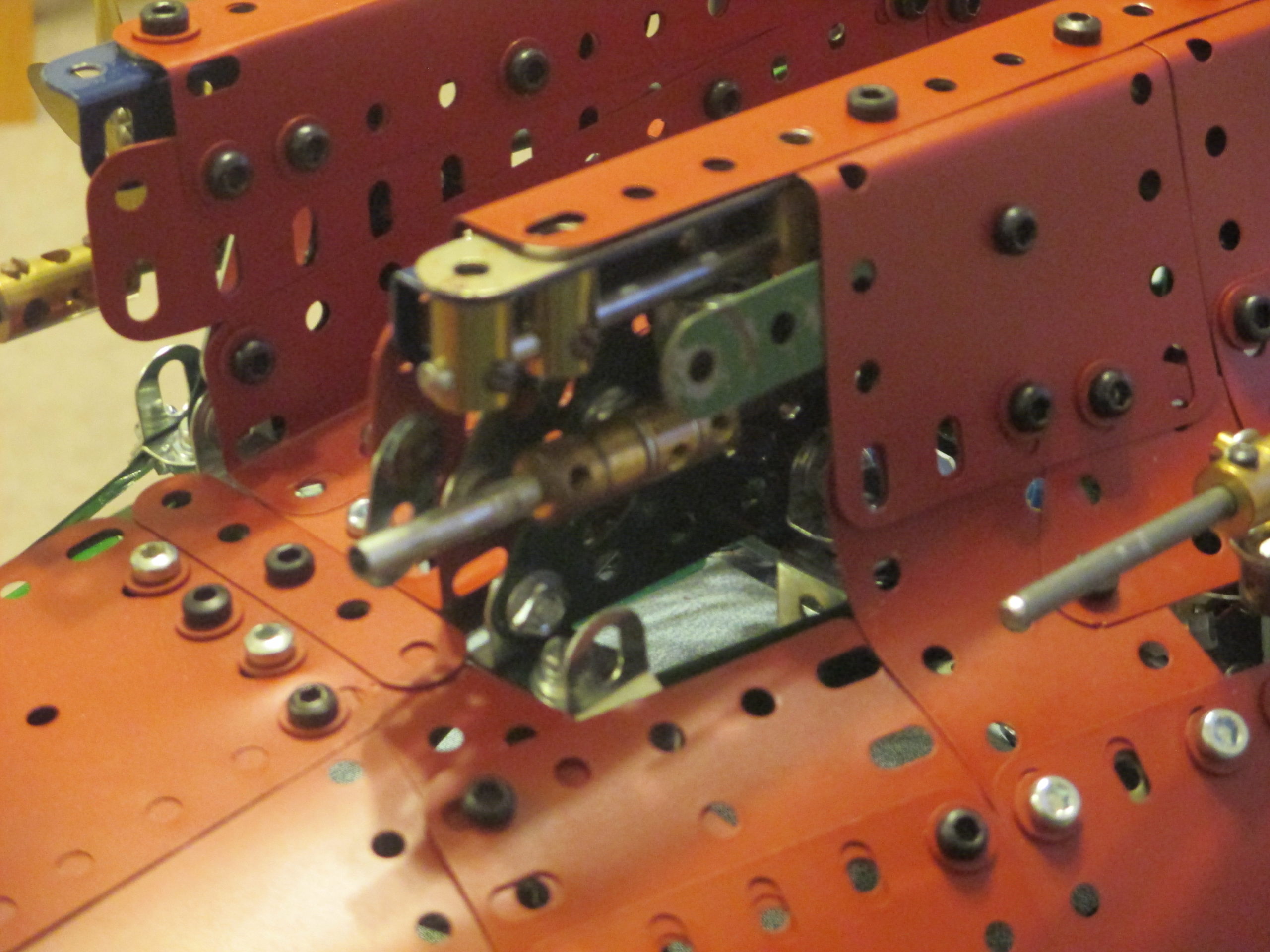
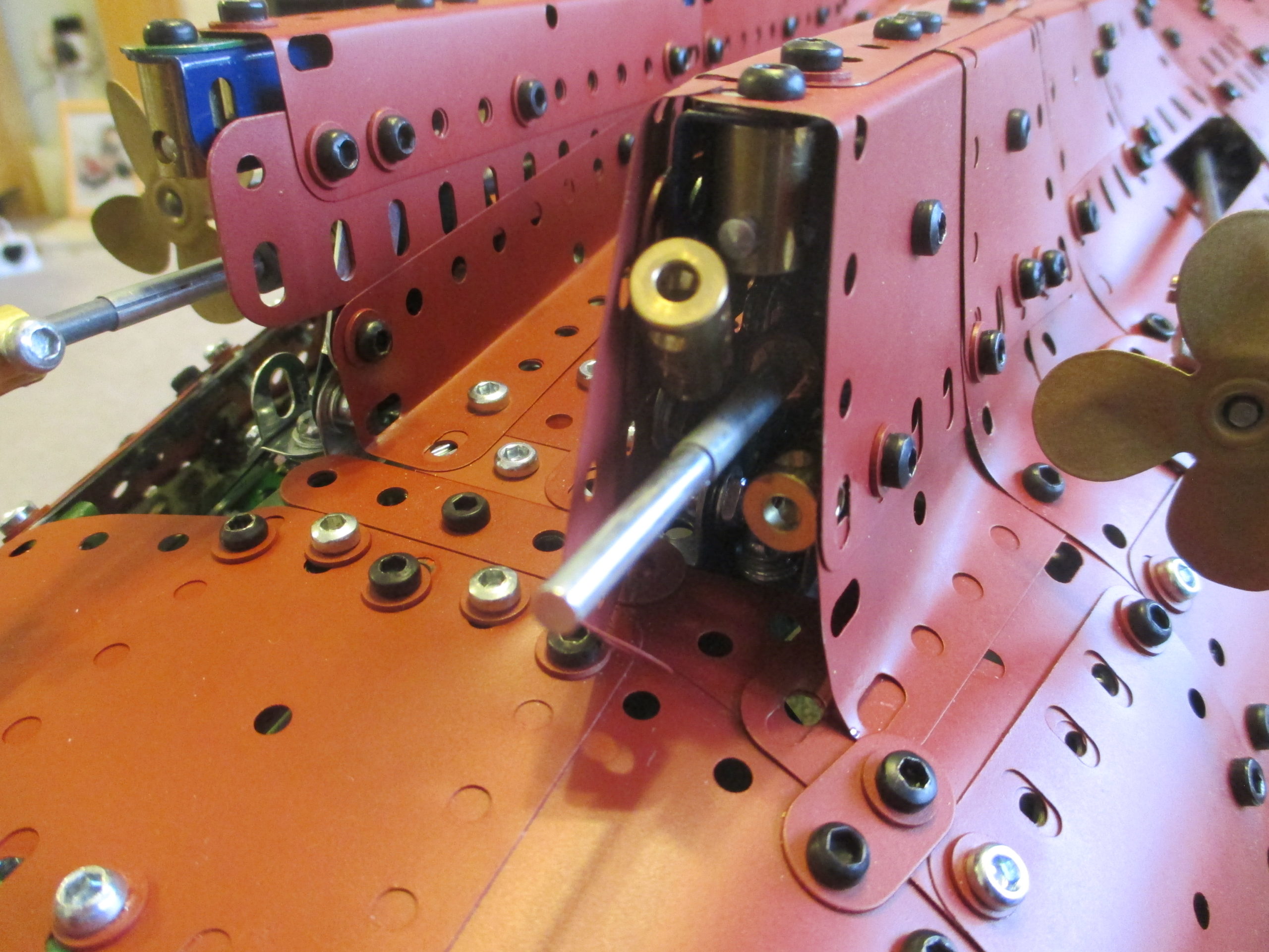
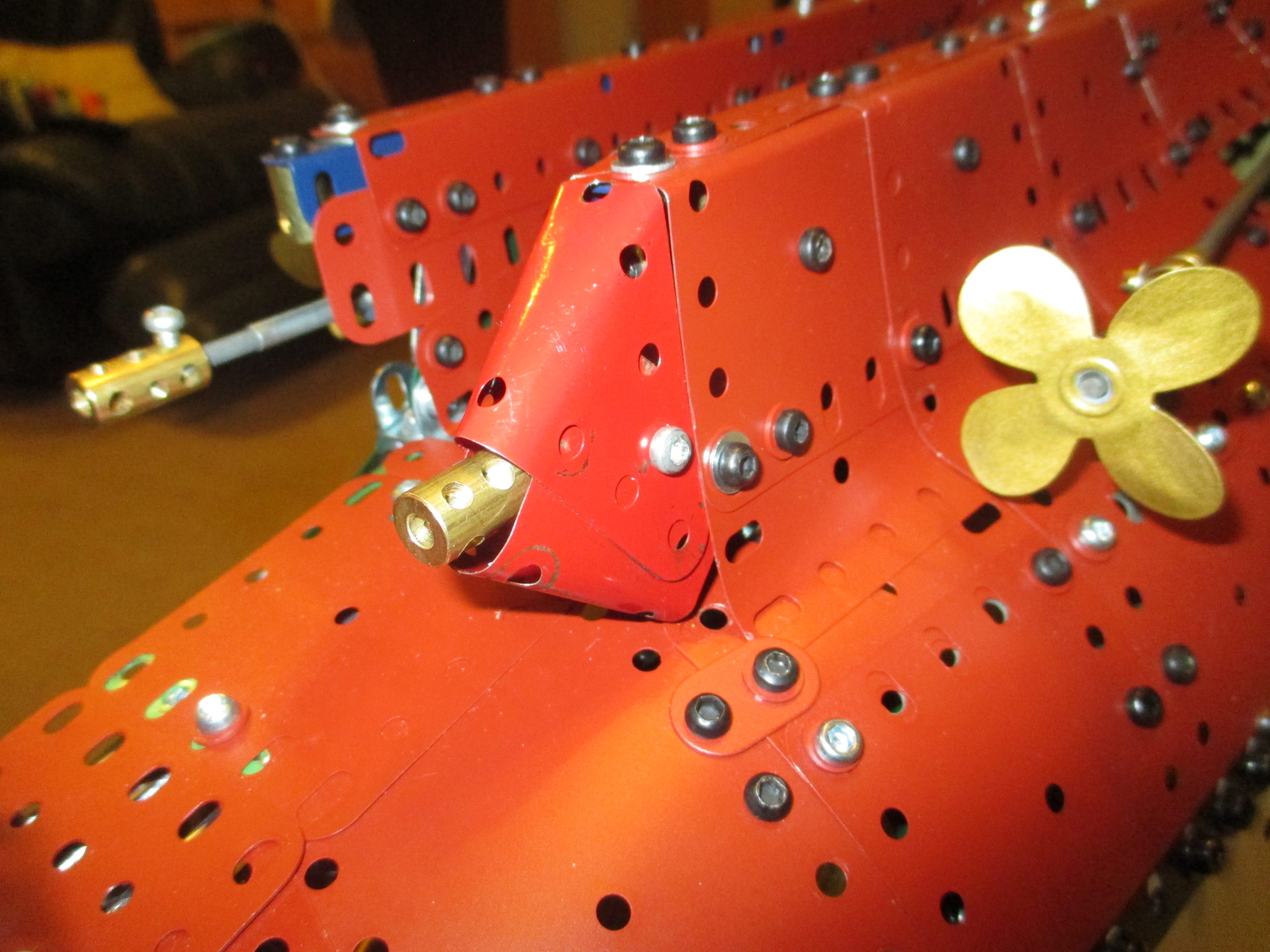
Accommodating the propeller shafts was a cladding nightmare. The two outboard ones which exit the hull cleanly weren’t too bad, but the inboard two are covered by strakes which line up with the rudders.
As if the shaping of the plates was not hard enough, having access to nuts became impossible as the strake section narrowed. The solution was again to use more brassware as captive nuts. Furthermore, the strakes needed to be robust enough for the weight of the section to rest on.
Some of the captive nuts are short threaded couplings along a supported rod, which provide a straight run. Others are ordinary couplings used to join adjacent plates. The ends of each of the strakes are closed off using two different triangular plates plus one 2½ x 1½ plate, made as subassemblies and attached using the captive nuts.
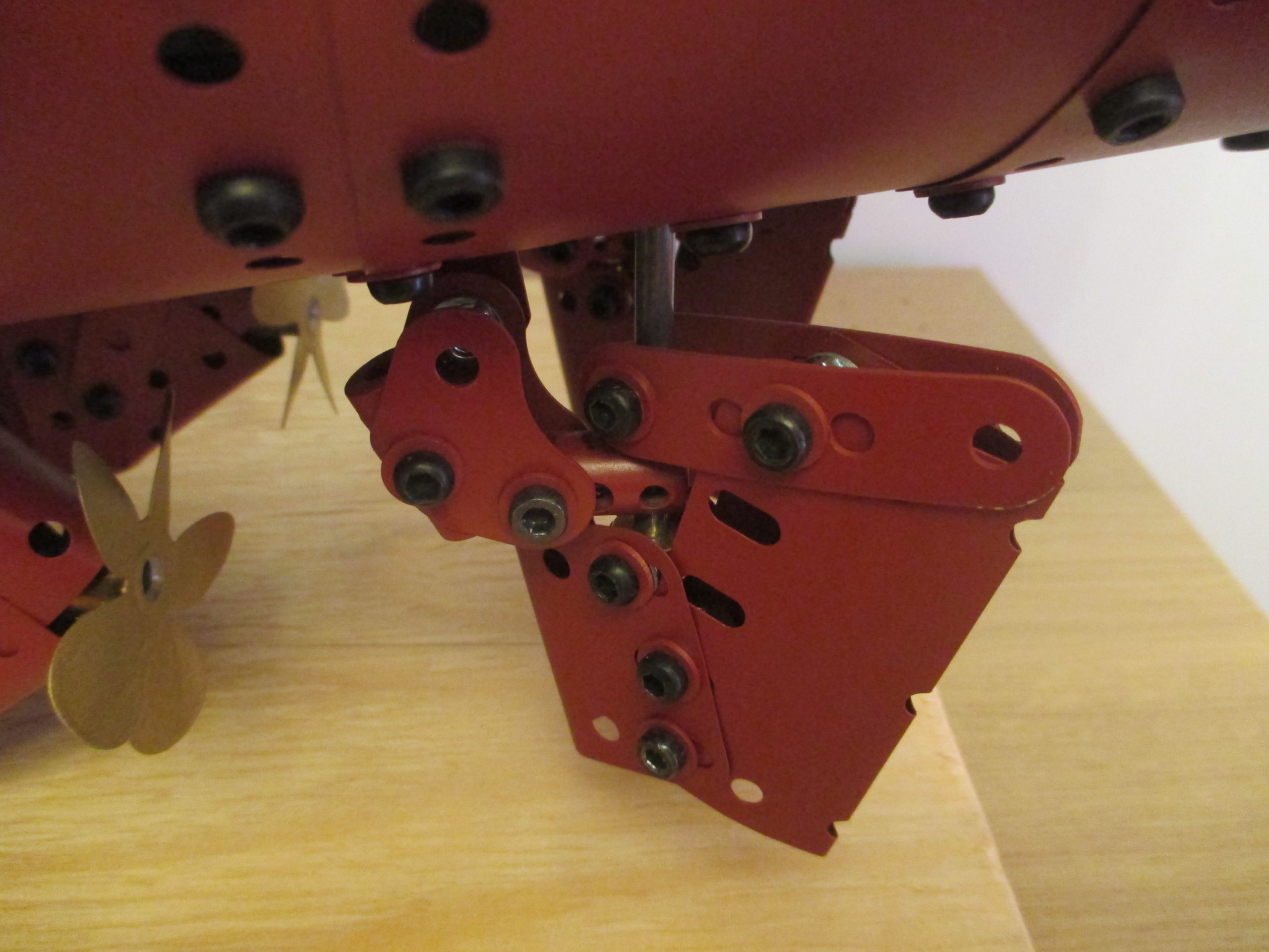
The rudders each have a small fixed portion as per the real ship, which provides a bearing location for the rudder shaft, but is only a cosmetic support as each shaft has two good bearings higher up.
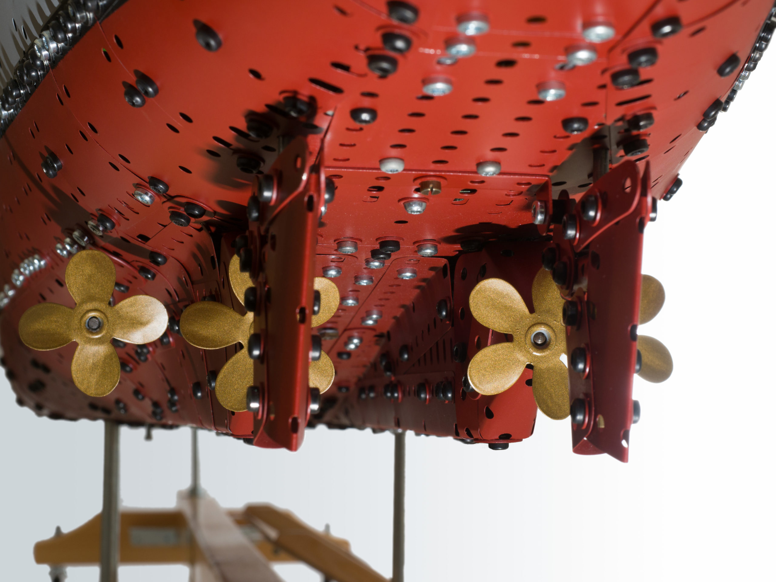
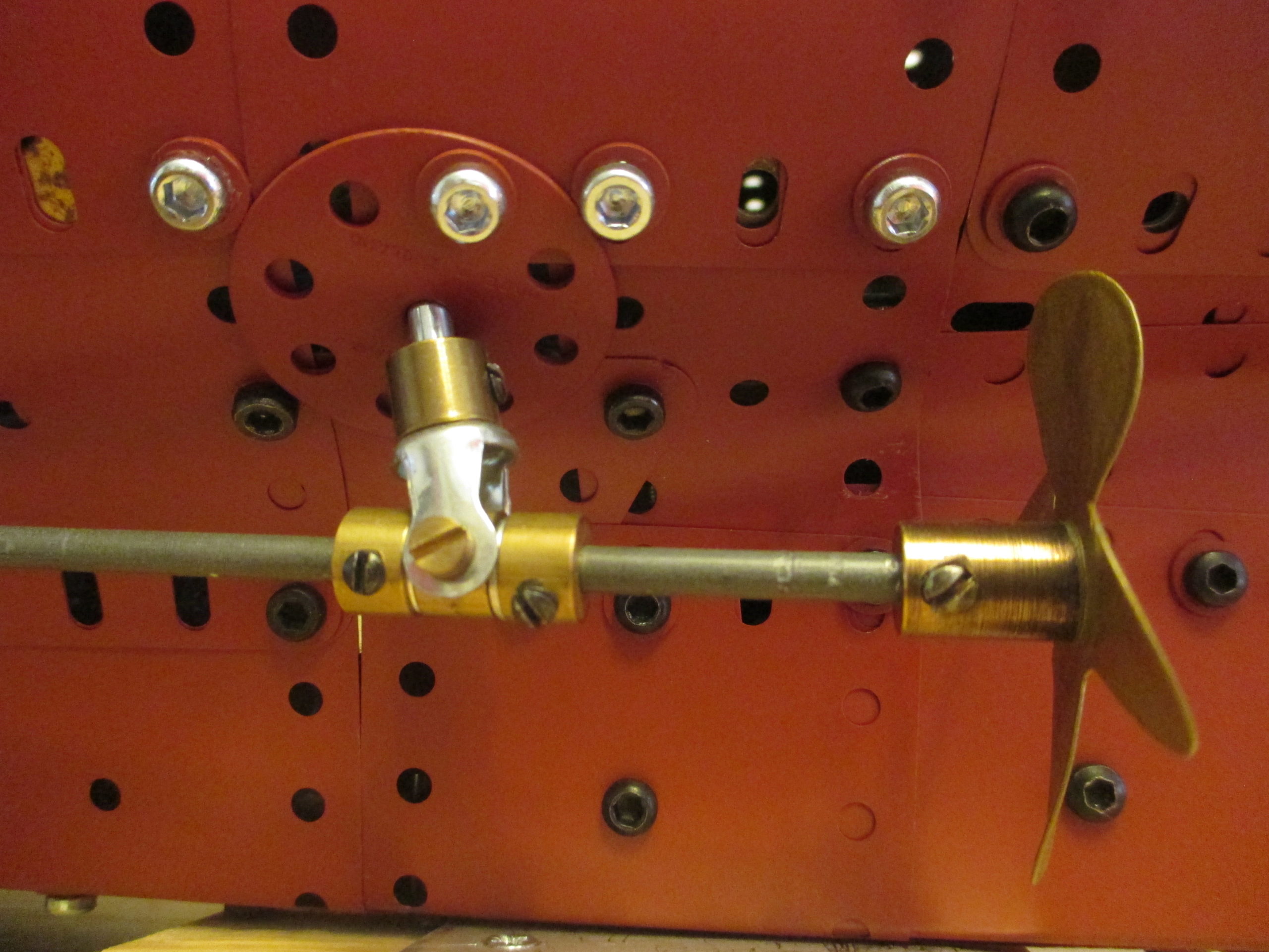
The propellers themselves have been fashioned from the conical centre of 2½ inch Meccano tin wheels. 4 and 5 bladed templates were created and printed out onto paper, which were then cut out and glued onto the face of each disc. Using tin snips and files, the shapes were cut from the disc leaving the brass boss in place. After twisting into shape and painting with Humbrol bronze paint, the end result is a very pleasing set of propellers.
There were irregular shaped gaps around the supports for the outboard propeller shafts. These have been closed off using wheel discs formed to match the curving profile. The discs' centre holes had to be deformed somewhat to allow the rods to pass through at an angle.
The view of the stern seen from below, with the sloping/tapering central tunnel, the propeller housings and the sweeping curves is the bit of the hull I’m most pleased with, but is rarely seen by others due to the awkward viewpoint.
By now a new way of transporting the sections in the car was needed to prevent damage. Paper cut-outs representing each section’s plan area (plus clearance margin) were made and placed in the back of my car to find the most appropriate layout. This just leaves enough space for 2 small overnight bags, and a couple of plastic tubs for tools and spares.
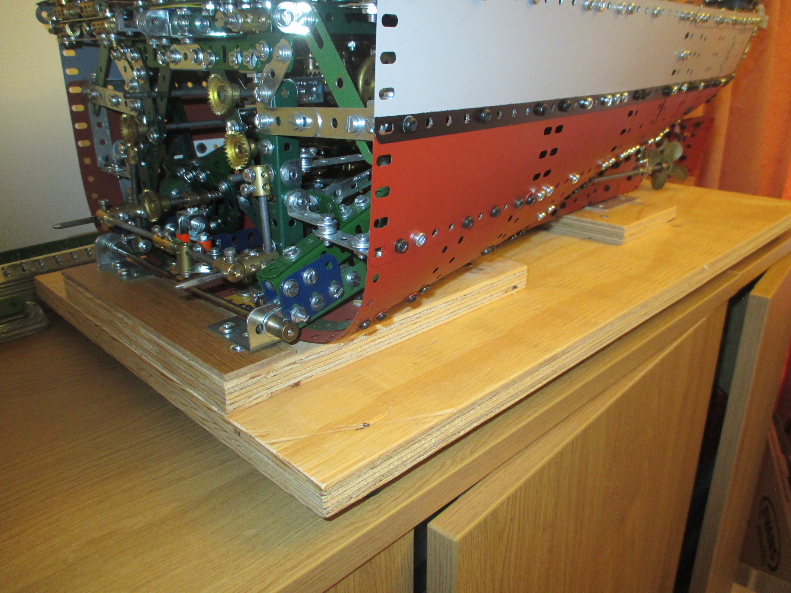
The superstructure and stern sections have bespoke plywood bases to sit on for transport, with rubber feet to stop them from sliding around in the car. The bow section has a crudely made cradle which I never bothered to remake properly as it does the job OK as it is.
The bow and stern sections anchor to the bases utilising the same structural attachment points used for section assembly. Drifts are used to pin the sections in place. The front of the bow also has a wooden wedge to secure it from lateral movement.
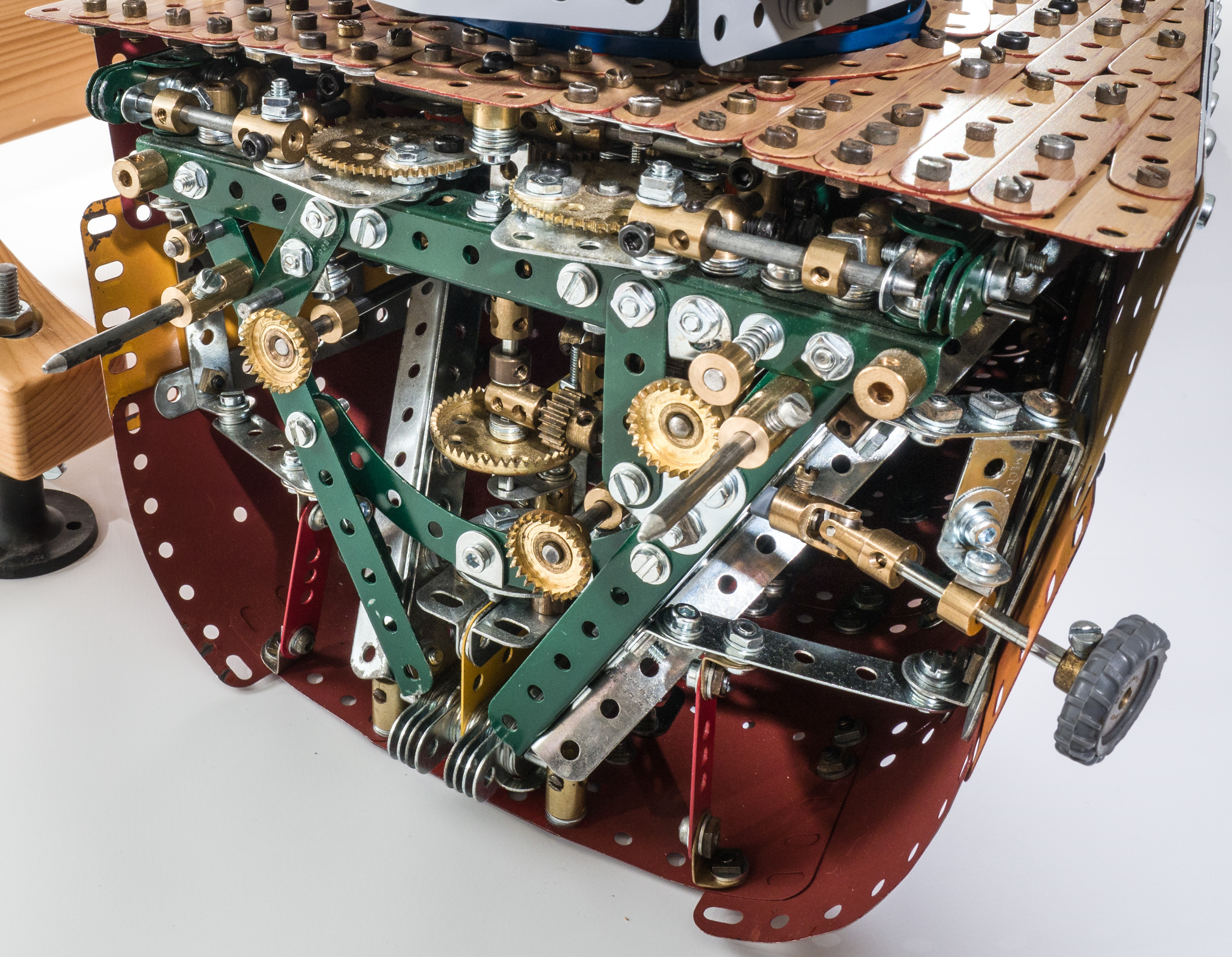
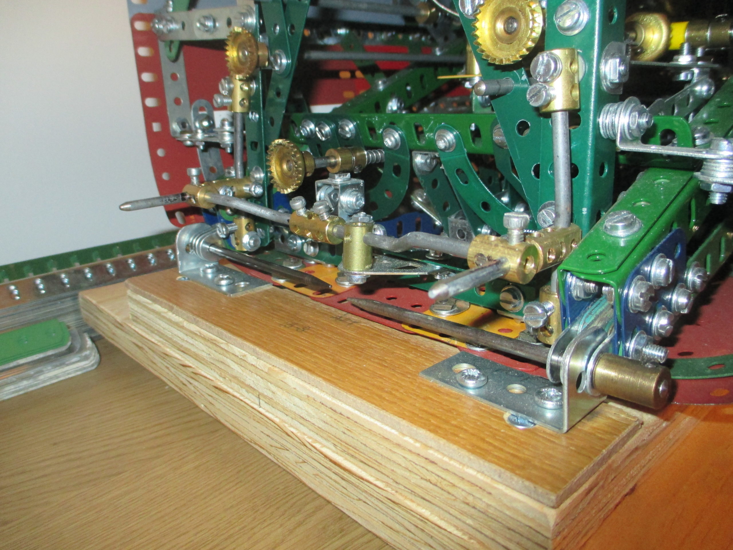
With all the hull plated, aligning the pin joints properly whilst holding the (not inconsiderable) weight of the bow or stern sections became too difficult even as a two person job. So a late modification was included. The bow and stern joint faces now include tapered guide pins sticking straight out to aid assembly.
The long tapered pins engage in structure holes in the centre section before visibility is obscured. This allows each section to be pushed into place with the multi-finger pin joints meshing together and with the cross pin holes aligned allowing the connection pins to be easily slid into place. Assembly is now in theory a one man job, but in practice a good deal easier with two.
